December 2019
Service and Repair Manual
Platform Components
Part No. 1300669GT
SX
™
-150
37
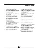
How to R eplace the Platform Overload Load C ell
How to Replace the Load Cell
Sensor
Note: The preload adjustment should only be
performed after the load cell sensor has been
replaced.
1 Remove all equipment or tools from the
platform. Remove the welder if equipped.
2 At the platform, remove the plastic instruction
holder from the document mount plate.
3 Tag and disconnect the load cell sensor
harness.
4 Loosen the jam nut securing the load cell
sensor foot and rotate the foot screw
clockwise to remove the preload.
5 Remove the fasteners securing the load cell
sensor and remove the sensor.
Install the new Load Cell Sensor
6 Screw the foot with jam nut into the top of the
load cell sensor until the foot bolt extends out
of the bottom of the sensor.The foot should
not contact the flex plate when assembling
onto the platform support.
7 Assemble the load cell and foot assembly to
the platform and securely tighten the two
mounting screws. Torque the bolts to
101 ft-lbs / 137 Nm.
Set the Load Cell Sensor Preload
8 Rotate the foot screw counter clockwise until
the foot just contacts the flex plate (finger
tight).
9 Using an open end wrench, continue to rotate
the foot counter clockwise an additional
1/2 turn (180°). Then, while holding the foot
bolt, securely tighten the jam nut. Torque the
jam nut to 55 ft-lbs / 75 Nm.
10 Attach the load cell sensor harness.
11 Install the plastic instruction holder.
12 Calibrate the platform overload system. Refer
to Repair Procedure
How to Calibrate the
Platform Overload System
.
2-6
Platform Overload Recovery
Message
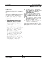
If the ground controls LCD screen displays
OVERLOAD RECOVERY, the emergency lowering
system has been used while the platform was
overloaded.
How to Clear the Platform
Overload Recovery Message
Note: This message shall be cleared by a person
trained and qualified on the troubleshooting and
repair of this machine.
Note: Use the following chart to identify the
description of each LCD screen control button used
in this procedure.
Plus
Minus
Previous
Enter
1 Turn the key switch to the off position.
2 Press and hold the
enter
button on the ground
control panel while turning the key switch to
ground controls. Hold the
enter
button for
approximately 5 seconds.
Summary of Contents for Genie SX-150
Page 105: ...December 2019 Service and Repair Manual Manifolds Part No 1300669GT SX 150 93 ...
Page 107: ...December 2019 Service and Repair Manual Manifolds Part No 1300669GT SX 150 95 ...
Page 109: ...December 2019 Service and Repair Manual Manifolds Part No 1300669GT SX 150 97 ...
Page 117: ...December 2019 Service and Repair Manual Part No 1300669GT SX 150 105 ...
Page 119: ...December 2019 Service and Repair Manual Part No 1300669GT SX 150 107 ...
Page 122: ...Service and Repair Manual December 2019 Manifolds 110 SX 150 Part No 1300669GT ...
Page 124: ...Service and Repair Manual December 2019 Manifolds 112 SX 150 Part No 1300669GT ...
Page 229: ...December 2019 Service and Repair Manual 217 Control Circuits Horn ...
Page 230: ...Service and Repair Manual December 2019 218 SX 150 Part No 1300669GT Control Circuits Horn ...
Page 231: ...December 2019 Service and Repair Manual Part No 1300669GT SX 150 219 Control Circuits Power ...
Page 232: ...Service and Repair Manual December 2019 220 Control Circuits Power ...
Page 233: ...December 2019 Service and Repair Manual 221 Control Circuits Can Bus ...
Page 234: ...Service and Repair Manual December 2019 222 SX 150 Part No 1300669GT Control Circuits Can Bus ...
Page 236: ...Service and Repair Manual December 2019 224 Control Circuits Deutz TD2011L04i Engine ...
Page 237: ...December 2019 Service and Repair Manual 225 Control Circuits Deutz TD 2 9 L4Engine ...
Page 240: ...Service and Repair Manual December 2019 228 Control Circuits Perkins 1104D 44T Engine ...
Page 241: ...December 2019 Service and Repair Manual 229 Control Circuits Perkins 854F 34T Engine ...
Page 244: ...Service and Repair Manual December 2019 232 Control Circuits Axle Extend Retract ...
Page 245: ...December 2019 Service and Repair Manual 233 Control Circuits Steering ...
Page 247: ...December 2019 Service and Repair Manual Part No 1300669GT SX 150 235 Control Circuits Propel ...
Page 248: ...Service and Repair Manual December 2019 236 Control Circuits Propel ...
Page 249: ...December 2019 Service and Repair Manual 237 Control Circuits Turntable Rotate ...
Page 252: ...Service and Repair Manual December 2019 240 Control Circuits Boom Up Down ...
Page 253: ...December 2019 Service and Repair Manual 241 Control Circuits Boom Extend Retract ...
Page 261: ...December 2019 Service and Repair Manual 249 Control Circuits Recovery PLD ...
Page 264: ...Service and Repair Manual December 2019 252 Control Circuits Telematics ...
Page 265: ...December 2019 Service and Repair Manual 253 Generator Receptacle Wiring ANSI CSA ...
Page 268: ...Service and Repair Manual December 2019 256 Generator Receptacle Wiring CE ...
Page 269: ...December 2019 Service and Repair Manual 257 Perkins 1104D 44T Engine Electrical Schematic ...
Page 272: ...Service and Repair Manual December 2019 260 Perkins 854F 34T Engine Electrical Schematic ...
Page 273: ...December 2019 Service and Repair Manual 261 Perkins 854F 34T Engine Harness ...
Page 276: ...Service and Repair Manual December 2019 264 Deutz TD 2 9 L4 Engine Electrical Schematic ...
Page 277: ...December 2019 Service and Repair Manual 265 Deutz TD 2 9 L4 Engine Harness ...
Page 279: ...December 2019 Service and Repair Manual 267 Hydraulic Schematic ...
Page 280: ...Service and Repair Manual December 2019 268 Hydraulic Schematic ...
Page 282: ......

