December 2019
Service and Repair Manual
Platform Components
Part No. 1300669GT
SX
™
-150
33
2-4
Platform Level Sensor
The platform level sensor is mounted to the side of
the platform rotator. The platform level sensor is
monitored by the control system to maintain a level
platform through boom range of motion. If a
platform level sensor is replaced, it must be
calibrated prior to machine operation.
How to Calibrate the Platform
Level Sensor
Note: Perform this procedure with the machine on
a firm, level surface.
Note: Perform this procedure with the boom in the
stowed position.
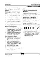
Note: Use the following chart to identify the
description of each LCD screen control button used
in this procedure.
Plus
Minus
Previous
Enter
1 Secure a digital level to one of the side railings
of the platform.
2 Start the machine and level the platform to
gravity. Turn the machine off.
3 Open the ground control box.
4 Locate the calibration toggle switch at the top
of the ground control box. Activate calibration
mode by moving the toggle switch in the left
direction.
5 Temporarily install a control box door retaining
fastener between the door and the box to
prevent the control box door from moving the
toggle switch while calibrating the machine.
6 Insert the key into the bypass/recovery key
switch and turn it to the bypass position.
Note: The platform level calibration value will not
be saved correctly unless the key switch is in the
bypass position and the calibration toggle switch is
activated.
7 Press and hold the
enter
button on the ground
control panel while turning the key switch to
ground controls. Hold the
enter
button for
approximately 5 seconds.
8 Enter sensor calibration mode by pressing the
buttons at the ground controls in the following
sequence:
(plus)(enter)(enter)(plus)
.
9 Press the
enter
or
previous
button on the
LCD screen until SET
PLATFORM
LEVEL
SENSOR
TO
GRAVITY is displayed.
10 Press the
plus
button to select YES, then
press the
enter
button to accept.
Note: The platform level sensor is calibrated at the
factory for the correct millivolt/degree and will not
need to be adjusted.
Summary of Contents for Genie SX-150
Page 105: ...December 2019 Service and Repair Manual Manifolds Part No 1300669GT SX 150 93 ...
Page 107: ...December 2019 Service and Repair Manual Manifolds Part No 1300669GT SX 150 95 ...
Page 109: ...December 2019 Service and Repair Manual Manifolds Part No 1300669GT SX 150 97 ...
Page 117: ...December 2019 Service and Repair Manual Part No 1300669GT SX 150 105 ...
Page 119: ...December 2019 Service and Repair Manual Part No 1300669GT SX 150 107 ...
Page 122: ...Service and Repair Manual December 2019 Manifolds 110 SX 150 Part No 1300669GT ...
Page 124: ...Service and Repair Manual December 2019 Manifolds 112 SX 150 Part No 1300669GT ...
Page 229: ...December 2019 Service and Repair Manual 217 Control Circuits Horn ...
Page 230: ...Service and Repair Manual December 2019 218 SX 150 Part No 1300669GT Control Circuits Horn ...
Page 231: ...December 2019 Service and Repair Manual Part No 1300669GT SX 150 219 Control Circuits Power ...
Page 232: ...Service and Repair Manual December 2019 220 Control Circuits Power ...
Page 233: ...December 2019 Service and Repair Manual 221 Control Circuits Can Bus ...
Page 234: ...Service and Repair Manual December 2019 222 SX 150 Part No 1300669GT Control Circuits Can Bus ...
Page 236: ...Service and Repair Manual December 2019 224 Control Circuits Deutz TD2011L04i Engine ...
Page 237: ...December 2019 Service and Repair Manual 225 Control Circuits Deutz TD 2 9 L4Engine ...
Page 240: ...Service and Repair Manual December 2019 228 Control Circuits Perkins 1104D 44T Engine ...
Page 241: ...December 2019 Service and Repair Manual 229 Control Circuits Perkins 854F 34T Engine ...
Page 244: ...Service and Repair Manual December 2019 232 Control Circuits Axle Extend Retract ...
Page 245: ...December 2019 Service and Repair Manual 233 Control Circuits Steering ...
Page 247: ...December 2019 Service and Repair Manual Part No 1300669GT SX 150 235 Control Circuits Propel ...
Page 248: ...Service and Repair Manual December 2019 236 Control Circuits Propel ...
Page 249: ...December 2019 Service and Repair Manual 237 Control Circuits Turntable Rotate ...
Page 252: ...Service and Repair Manual December 2019 240 Control Circuits Boom Up Down ...
Page 253: ...December 2019 Service and Repair Manual 241 Control Circuits Boom Extend Retract ...
Page 261: ...December 2019 Service and Repair Manual 249 Control Circuits Recovery PLD ...
Page 264: ...Service and Repair Manual December 2019 252 Control Circuits Telematics ...
Page 265: ...December 2019 Service and Repair Manual 253 Generator Receptacle Wiring ANSI CSA ...
Page 268: ...Service and Repair Manual December 2019 256 Generator Receptacle Wiring CE ...
Page 269: ...December 2019 Service and Repair Manual 257 Perkins 1104D 44T Engine Electrical Schematic ...
Page 272: ...Service and Repair Manual December 2019 260 Perkins 854F 34T Engine Electrical Schematic ...
Page 273: ...December 2019 Service and Repair Manual 261 Perkins 854F 34T Engine Harness ...
Page 276: ...Service and Repair Manual December 2019 264 Deutz TD 2 9 L4 Engine Electrical Schematic ...
Page 277: ...December 2019 Service and Repair Manual 265 Deutz TD 2 9 L4 Engine Harness ...
Page 279: ...December 2019 Service and Repair Manual 267 Hydraulic Schematic ...
Page 280: ...Service and Repair Manual December 2019 268 Hydraulic Schematic ...
Page 282: ......

