June 2021
Service and Repair Manual
Engines
Part No. 1306587GT
GS
™
-84 • GS
™
-90
51
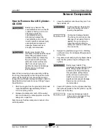
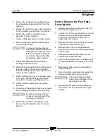
4 Remove the exhaust pipe, located between
the exhaust manifold and muffler, from the
machine.
5 Remove the medium pressure filter assembly
from the muffler mount and lay it to the side.
6 Remove the muffler and muffler mount
assembly from the machine.
7 Center a lifting jack under the engine oil pan.
8 Place a wood block between the lifting jack
and the engine oil pan.
Component damage hazard.
The engine oil pan can become
damaged if the engine is raised
with the lifting jack without the
wood block between the lifting
jack and the engine oil pan.
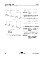
9 Remove the fasteners securing the bell
housing to the slide out tray.
10 Raise the engine slightly with the lifting jack to
take the pressure off the rubber vibration
isolators under the bell housing. Remove the
rubber vibration isolators.
11 Attach a lifting strap from an overhead crane
to the pump and bell housing assembly for
support. Do not apply any lifting pressure.
12 Remove all of the bell housing to engine
fasteners.
13 Carefully pull the pump and bell housing away
from the engine and secure it from moving.
Component damage hazard.
Hoses can be damaged if they
are kinked or pinched.
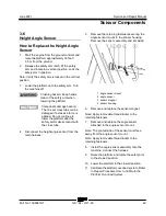
14 Remove the flex plate mounting fasteners,
then remove the flex plate from the engine
flywheel.
How to Remove the Flex Plate - Deutz Models
How to Remove the Flex Plate -
Deutz Models
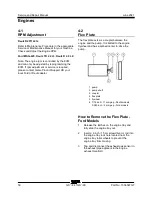
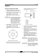
1 Release the latches on the engine tray and
fully slide the engine tray out.
2 Insert a 6 inch / 15 cm screwdriver or rod into
the engine tray lock hole located near the
engine tray roller wheels to prevent the
engine tray from moving.
3 Remove the hose clamp from the air cleaner
hose that connects to the engine.
4 Remove the air filter mounting fasteners.
Remove the air filter from the engine and lay it
off to the side.
5 Remove the exhaust pipe clamp from the
exhaust pipe support bracket.
6 Attach a lifting strap from an overhead crane
to the pump assembly for support. Do not lift
it.
7 Remove all of the pump mounting plate to
engine fasteners.
8 Carefully pull the pump assembly away from
the engine and secure it from moving.
Component damage hazard.
Hoses can be damaged if they
are kinked or pinched.
9 Remove the flex plate mounting fasteners,
then remove the flex plate from the engine
flywheel.
Summary of Contents for Genie GS-3384
Page 185: ...June 2021 Service and Repair Manual 171 Ford MSG 425 Engine Wire Harness...
Page 188: ...Service and Repair Manual June 2021 174 Deutz D 2 9 L4 Engine Wire Harness...
Page 189: ...June 2021 Service and Repair Manual 175 Deutz TD 2 2 L3 Engine Wire Harness...
Page 192: ...Service and Repair Manual June 2021 178 Deutz TD 2 2 L3 Engine Wire Harness...
Page 193: ...June 2021 Service and Repair Manual 179 Hydraulic Schematic...
Page 194: ...Service and Repair Manual June 2021 180 GS 84 GS 90 Part No 1306587GT Hydraulic Schematic...
Page 195: ...June 2021 Service and Repair Manual Part No 1306587GT GS 84 GS 90 181 Hydraulic Schematic...
Page 196: ...Service and Repair Manual June 2021 182 Hydraulic Schematic...
Page 197: ...June 2021 Service and Repair Manual 183 Electrical Schematic Ford Engine Models ANSI CSA...
Page 200: ...Service and Repair Manual June 2021 186 Electrical Schematic Ford Engine Models ANSI CSA...
Page 201: ...June 2021 Service and Repair Manual 187 Electrical Schematic Deutz Engine Models ANSI CSA...
Page 204: ...Service and Repair Manual June 2021 190 Electrical Schematic Deutz Engine Models ANSI CSA...
Page 206: ...Service and Repair Manual June 2021 192 Electrical Schematic SCON ANSI CSA...
Page 207: ...June 2021 Service and Repair Manual 193 Electrical Schematic Ford Engine Models AS CE...
Page 210: ...Service and Repair Manual June 2021 196 Electrical Schematic Ford Engine Models AS CE...
Page 211: ...June 2021 Service and Repair Manual 197 Electrical Schematic Deutz Engine Models AS CE...
Page 214: ...Service and Repair Manual June 2021 200 Electrical Schematic Deutz Engine Models AS CE...
Page 217: ......

