June 2021
Service and Repair Manual
Ground Controls
Part No. 1306587GT
GS
™
-84 • GS
™
-90
57
How to Determine the Revision Level
How to Determine the Revision
Level
1 Turn the key switch to ground control and pull
out the red Emergency Stop button to the on
position at both ground and platform controls.
Result: The revision level of the ECM will
appear in the LED display window.
How to Adjust the Stowed Drive Speed
How to Adjust the Stowed Drive
Speed
Tip-over hazard. Do not adjust
the lift and/or drive speed higher
than specified in this procedure.
Setting drive speed greater than
specifications could cause the
machine to tip over resulting in
death or serious injury.
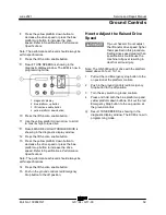
1 Pull out the red Emergency stop button to the
on position at the platform controls.
2 Push in the ground controls red Emergency
Stop button to the off position.
3 Turn the key switch to ground controls.
4 Press and hold both the blue platform up and
yellow platform down buttons. Pull out the red
Emergency Stop button to the on position at
the ground controls.
Result: TUNE SPEEDS is showing in the
diagnostic display window. The ECM is now in
programming mode.
5 Press the lift function enable button.
6 Use the yellow platform down arrow to scroll
to max fwd high speed drive.
Result: MAX FWD HIGH SPEED drive is
showing in the diagnostic display window.
7 Press the lift function enable button.
8 Press the yellow platform down button to
decrease the drive speed or press the blue
platform up button to increase the drive
speed. Refer to Specifications,
Performance
Specifications.
Note: The performance achieved should always be
within specifications.
9 Press the lift function enable button.
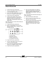
Result: TUNE SPEEDS is showing in the
diagnostic display window. The ECM is now in
programming mode.
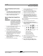
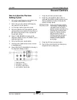
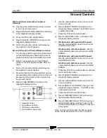
1 diagnostic display
2 blue platform up button
3 lift function enable button
4 yellow platform down button
10 Press the lift function enable button.
11 Use the yellow platform down arrow to scroll
to max rev high speed drive.
Result: MAX REV HIGH SPEED drive is
showing in the diagnostic display window.
Summary of Contents for Genie GS-3384
Page 185: ...June 2021 Service and Repair Manual 171 Ford MSG 425 Engine Wire Harness...
Page 188: ...Service and Repair Manual June 2021 174 Deutz D 2 9 L4 Engine Wire Harness...
Page 189: ...June 2021 Service and Repair Manual 175 Deutz TD 2 2 L3 Engine Wire Harness...
Page 192: ...Service and Repair Manual June 2021 178 Deutz TD 2 2 L3 Engine Wire Harness...
Page 193: ...June 2021 Service and Repair Manual 179 Hydraulic Schematic...
Page 194: ...Service and Repair Manual June 2021 180 GS 84 GS 90 Part No 1306587GT Hydraulic Schematic...
Page 195: ...June 2021 Service and Repair Manual Part No 1306587GT GS 84 GS 90 181 Hydraulic Schematic...
Page 196: ...Service and Repair Manual June 2021 182 Hydraulic Schematic...
Page 197: ...June 2021 Service and Repair Manual 183 Electrical Schematic Ford Engine Models ANSI CSA...
Page 200: ...Service and Repair Manual June 2021 186 Electrical Schematic Ford Engine Models ANSI CSA...
Page 201: ...June 2021 Service and Repair Manual 187 Electrical Schematic Deutz Engine Models ANSI CSA...
Page 204: ...Service and Repair Manual June 2021 190 Electrical Schematic Deutz Engine Models ANSI CSA...
Page 206: ...Service and Repair Manual June 2021 192 Electrical Schematic SCON ANSI CSA...
Page 207: ...June 2021 Service and Repair Manual 193 Electrical Schematic Ford Engine Models AS CE...
Page 210: ...Service and Repair Manual June 2021 196 Electrical Schematic Ford Engine Models AS CE...
Page 211: ...June 2021 Service and Repair Manual 197 Electrical Schematic Deutz Engine Models AS CE...
Page 214: ...Service and Repair Manual June 2021 200 Electrical Schematic Deutz Engine Models AS CE...
Page 217: ......


