


June 2021
Service and Repair Manual
Scissor Components
Part No. 1306587GT
GS
™
-84 • GS
™
-90
23
3-1
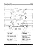
Scissor Assembly, GS-3384 and
3390
How to Disassemble the Scissor Assembly
How to Disassemble the Scissor
Assembly
Bodily injury hazard. This
procedure requires specific repair
skills, lifting equipment and a
suitable workshop. Attempting
this procedure without these
skills and tools could result in
death or serious injury and
significant component damage.
Dealer service is strongly
recommended.
Note: When removing a hose assembly or fitting,
the O-ring (if equipped) on the fitting and/or hose
end must be replaced. All connections must be
torqued to specification during installation. Refer to
Specifications,
Hydraulic Hose and Fitting Torque
Specifications.
1 Remove the platform. Refer to Repair
Procedure,
How to Remove the Platform.
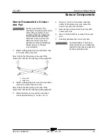
2 Remove the cables from the platform
centering link (index #1) at the hydraulic tank
side of the machine.
3 Remove the pin retaining fasteners from the
lift cylinder rod-end pivot pin (index #12). Do
not remove the pin.
4 Attach a lifting strap from an overhead crane
to the lifting eye at the rod end of the lift
cylinder.
5 Use a soft metal drift to remove the lift
cylinder rod-end pivot pin (index #12). Lower
the rod end of the lift cylinder down onto the
number 2 inner arm (index #6).
Crushing hazard. The lift
cylinder will fall if not properly
supported when the pivot pin is
removed.
6 Tag, disconnect and plug the hydraulic hoses
from the lift cylinder. Cap the fittings on the
cylinder.
Bodily injury hazard. Spraying
hydraulic oil can penetrate and
burn skin. Loosen hydraulic
connections very slowly to allow
the oil pressure to dissipate
gradually. Do not allow oil to
squirt or spray.
7 Cut the zip ties attaching the hydraulic hoses
to the lift cylinder. Lay the hoses out of the
way.
Component damage hazard.
Hoses can be damaged if they
are kinked or pinched.
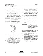
8 Remove the cables from the number 2 inner
arm (index #6) and lay the cables off to the
side.
Component damage hazard.
Cables can be damaged if they
are kinked or pinched.
9 Remove the pin retaining fasteners from the
cable tray pivot pin at the number 3 inner arm
(index #2).
Summary of Contents for Genie GS-3384
Page 185: ...June 2021 Service and Repair Manual 171 Ford MSG 425 Engine Wire Harness...
Page 188: ...Service and Repair Manual June 2021 174 Deutz D 2 9 L4 Engine Wire Harness...
Page 189: ...June 2021 Service and Repair Manual 175 Deutz TD 2 2 L3 Engine Wire Harness...
Page 192: ...Service and Repair Manual June 2021 178 Deutz TD 2 2 L3 Engine Wire Harness...
Page 193: ...June 2021 Service and Repair Manual 179 Hydraulic Schematic...
Page 194: ...Service and Repair Manual June 2021 180 GS 84 GS 90 Part No 1306587GT Hydraulic Schematic...
Page 195: ...June 2021 Service and Repair Manual Part No 1306587GT GS 84 GS 90 181 Hydraulic Schematic...
Page 196: ...Service and Repair Manual June 2021 182 Hydraulic Schematic...
Page 197: ...June 2021 Service and Repair Manual 183 Electrical Schematic Ford Engine Models ANSI CSA...
Page 200: ...Service and Repair Manual June 2021 186 Electrical Schematic Ford Engine Models ANSI CSA...
Page 201: ...June 2021 Service and Repair Manual 187 Electrical Schematic Deutz Engine Models ANSI CSA...
Page 204: ...Service and Repair Manual June 2021 190 Electrical Schematic Deutz Engine Models ANSI CSA...
Page 206: ...Service and Repair Manual June 2021 192 Electrical Schematic SCON ANSI CSA...
Page 207: ...June 2021 Service and Repair Manual 193 Electrical Schematic Ford Engine Models AS CE...
Page 210: ...Service and Repair Manual June 2021 196 Electrical Schematic Ford Engine Models AS CE...
Page 211: ...June 2021 Service and Repair Manual 197 Electrical Schematic Deutz Engine Models AS CE...
Page 214: ...Service and Repair Manual June 2021 200 Electrical Schematic Deutz Engine Models AS CE...
Page 217: ......


