


June 2021
Service and Repair Manual
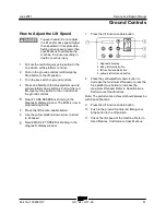
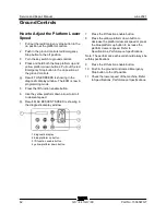
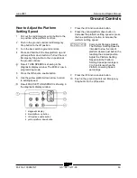
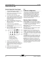
Ground Controls
Part No. 1306587GT
GS
™
-84 • GS
™
-90
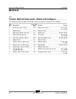
71
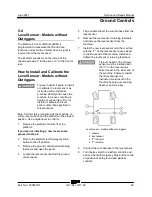
5-5
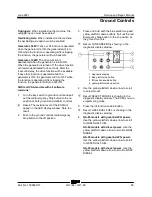
Level Sensor - Models with
Outriggers
The Electronic Control Module (ECM) is
programmed to deactivate the lift and drive
functions and activate an alarm when a signal is
received from the level sensor.
When the outriggers are stowed, the tilt alarm
sounds when the incline of the chassis exceeds 2°
to the side.
When the outriggers are deployed, the tilt alarm
sounds when the incline of the chassis exceeds
0.8° to the side.
At all times, the tilt alarm sounds when the incline
of the chassis exceeds 3° to the front or rear.
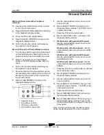
How to Install and Calibrate the Level Sensor - Models with Outriggers
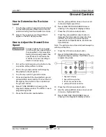
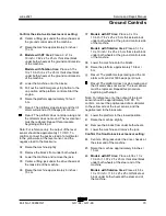
How to Install the Outrigger Level
Sensor - Models with Outriggers
Tip-over hazard. Failure to install
or calibrate the level sensor as
instructed will compromise
machine stability and cause the
machine to tip over, resulting in
death or serious injury. Do not
install or calibrate the level
sensor other than specified in
this procedure.
Note: Perform this procedure with the machine on
a firm, level surface that is free of obstructions.
1 Remove the platform controls from the
platform.
2 Remove the ground control panel retaining
fasteners and open the panel.
3 Locate the level sensor behind the ground
control panel.
4 Disconnect the platform controls from the
machine at the platform.
5 Open the large ground control panel door and
locate the Electronic Control Module (ECM)
wire harness to platform controls wire harness
connection below the ground controls.
6 Tag and disconnect the platform controls wire
harness from the ECM wire harness.
7 Securely connect the platform controls to the
ECM wire harness.
If you are not installing a new level sensor,
proceed to step 12.
Install the level sensor:
8 Tag and disconnect the wire harness from the
level sensor.
9 Remove the level sensor retaining fasteners
and remove the level sensor from the
machine.
Summary of Contents for Genie GS-3384
Page 185: ...June 2021 Service and Repair Manual 171 Ford MSG 425 Engine Wire Harness...
Page 188: ...Service and Repair Manual June 2021 174 Deutz D 2 9 L4 Engine Wire Harness...
Page 189: ...June 2021 Service and Repair Manual 175 Deutz TD 2 2 L3 Engine Wire Harness...
Page 192: ...Service and Repair Manual June 2021 178 Deutz TD 2 2 L3 Engine Wire Harness...
Page 193: ...June 2021 Service and Repair Manual 179 Hydraulic Schematic...
Page 194: ...Service and Repair Manual June 2021 180 GS 84 GS 90 Part No 1306587GT Hydraulic Schematic...
Page 195: ...June 2021 Service and Repair Manual Part No 1306587GT GS 84 GS 90 181 Hydraulic Schematic...
Page 196: ...Service and Repair Manual June 2021 182 Hydraulic Schematic...
Page 197: ...June 2021 Service and Repair Manual 183 Electrical Schematic Ford Engine Models ANSI CSA...
Page 200: ...Service and Repair Manual June 2021 186 Electrical Schematic Ford Engine Models ANSI CSA...
Page 201: ...June 2021 Service and Repair Manual 187 Electrical Schematic Deutz Engine Models ANSI CSA...
Page 204: ...Service and Repair Manual June 2021 190 Electrical Schematic Deutz Engine Models ANSI CSA...
Page 206: ...Service and Repair Manual June 2021 192 Electrical Schematic SCON ANSI CSA...
Page 207: ...June 2021 Service and Repair Manual 193 Electrical Schematic Ford Engine Models AS CE...
Page 210: ...Service and Repair Manual June 2021 196 Electrical Schematic Ford Engine Models AS CE...
Page 211: ...June 2021 Service and Repair Manual 197 Electrical Schematic Deutz Engine Models AS CE...
Page 214: ...Service and Repair Manual June 2021 200 Electrical Schematic Deutz Engine Models AS CE...
Page 217: ......


