User Manual for
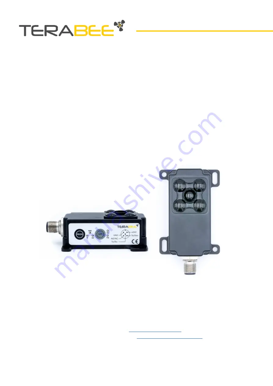
Terabee IND-TOF-1
Technical support:
support@terabee.com
Sales and commercial support:
terabee-sales@terabee.com
Page 1: ...User Manual for Terabee IND TOF 1 Technical support support terabee com Sales and commercial support terabee sales terabee com...
Page 2: ...ating mode 1 default 17 Description 17 Setup 17 Operation 18 LED signalization sequence 18 Operating mode 2 19 Description 19 Setup 19 Operation 20 Rolling buffer 5 measurements 20 LED signalization s...
Page 3: ...ng registers 39 DEVICE ADDRESS SETTING 39 MENU TIMEOUT 39 TIME DELAY FOR OPERATION MODE 40 NO NC ACTIVE REGION applicable to mode 3 4 and 5 40 OPERATING MODE SELECT 40 MODE 5 LIMIT VALUE 41 NO NC ON T...
Page 4: ...n be set using integrated teach in buttons to trigger alarms detect presence and movement count objects and more The sensor provides proximity notification with a classic NO NC switching output while...
Page 5: ...e for NO NC State Change 3 35 ms to 100 ms Electronics Supply Voltage V IN 24V 5 DC Current Consumption max V IN 24V DC 90 mA Warm up Time advised 15 min Initialization Time 1 s Interfaces Digital Out...
Page 6: ...cent lighting ambient temperature around 25 C Note that bright sunlight target surface reflectivity and other variables can affect sensor performance 2 Evaluated as one standard deviation over multipl...
Page 7: ...e product package Figure 2 contains the following items Terabee IND TOF 1 distance sensor Figure 2 Product package content Copyright Terabee 2019 Terabee 90 Rue Henri Fabre 01630 St Genis Pouilly Fran...
Page 8: ...the long M4 screw slots Figure 4 2 Back panel mount using the 2mm ledge on the front side of the sensor Figure 5 The first solution allows for easy surface attachment and rapid evaluation of the sens...
Page 9: ...example An optional 90 degree mounting bracket accessory is also available on the terabee website for angled attachment methods to existing industrial infrastructures Copyright Terabee 2019 Terabee 9...
Page 10: ...n your application Please note that mounting the sensor with a distance smaller than 70 cm from the measured object can affect the sensor absolute accuracy Mounting close to sources of heat or strong...
Page 11: ...ation sequence of the LEDs Figure 6 Operating buttons and LED indicators Table 2 Connector location and onboard operating buttons and indicators No Category Designator Description 1 Connection M12 con...
Page 12: ...inout Terabee IND TOF 1 uses an M12 A coded male connector 5 pins Figure 7 and Table 4 provide an overview of the connector pinout Figure 7 M12 5 pin connector pinout layout Table 4 Connector pinout d...
Page 13: ...tandard Maximum Power supply Voltage input DC 24 V 24 V 24 V Current consumption 50 mA 70 mA 90 mA Digital output levels NO NC in PNP NPN Voltage output DC 0 V 24 V Current consumption 450 mA Copyrigh...
Page 14: ...data use distinct pins both functions can be used either to complement each other or as separate functions For instance the switching output can act as a trigger for the master device e g Programmable...
Page 15: ...n as an object ENTERS the trigger zone Output remains triggered as long as the light beam in the trigger zone is broken Available via RS485 Modbus 4 3 thresholds Output is triggered as soon as an obje...
Page 16: ...er this is a configurable parameter 3 Operation mode marks the end of setup sensor is ready to perform detection under programmed trigger zones Please be aware that during setup a timeout default 30 s...
Page 17: ...d of View at the preferred background distance then hold the PROG button for 1 second The LED indicators Th1 and Th2 both GREEN will now go from ON to OFF status to confirm entering programming mode O...
Page 18: ...RED as long as the output is triggered Any movement beyond the background threshold will be ignored Figure 10 Mode 1 operation detection principle LED signalization sequence Table 7 Mode 1 LED signal...
Page 19: ...ed background distance then hold the PROG button for 1 second The LED indicators Th1 and Th2 both GREEN will now go from ON to OFF status to confirm entering programming mode Once the programming mode...
Page 20: ...ovement beyond the background threshold will be ignored The NO NC switching output activation time by default is set to 250 ms and can be modified using the NO NC on time parameter see Section 5 3 Fig...
Page 21: ...w 4 5 Operating mode 3 Description In mode 3 a switching window is taught in between the sensor and the background threshold The sensor is activated as soon as an object or a person enters the selecte...
Page 22: ...y a properly stored threshold The LED indicator Th2 will start blinking GREEN to signal that the sensor is ready for Threshold 2 Th2 setup Step 3 Set Threshold 2 Th2 Make sure that an object is fully...
Page 23: ...ut is activated The sensor will stay activated as long as the object remains in the set trigger zone Any movement beyond the background threshold will be ignored By default mode 3 offers detection cap...
Page 24: ...region 0 Switching output status NO NC active region 1 Between the sensors minimum distance 50 cm and the Threshold 1 Th1 stays continuously ON RED OFF ON Between Threshold 1 and Threshold 2 Th1 and...
Page 25: ...hat the device is ready for Threshold 2 registration Th1 Th2 LEDs stay continuously ON GREEN Indicates that setup is finalized and sensor is in operation mode 4 6 Operating mode 4 Description In mode...
Page 26: ...hold 1 then press the SET button The LED indicator Th2 will continuously stay ON GREEN to verify a properly stored threshold Once both thresholds are registered the sensor will go into Time delay for...
Page 27: ...shold 2 By changing the NO NC active region setting in sensor parameters see Section 5 3 the user can also set multiple trigger zones 1 from min sensor distance 50 cm to Threshold 1 and 2 from Thresho...
Page 28: ...round threshold distance Th1 and Th2 stay continuously ON GREEN OFF OFF Rolling buffer 5 measurements After an object has entirely left the light beam of the trigger zone the distance that was recorde...
Page 29: ...t the device is ready for Threshold 2 setup Th1 Th2 LEDs stay continuously ON GREEN Indicates that setup is finalized and sensor is in operation mode 4 7 Operating mode 5 Description A trigger zone is...
Page 30: ...X distance is programmable via the LIMIT VALUE parameter as described in Section 5 3 Step 3 Sensor is ready Both LED indicators Th1 and Th2 will turn continuously ON GREEN indicating that the setup is...
Page 31: ...e modified using the for NO NC on time parameter see Section 5 3 Figure 20 Mode 5 operation NO NC active region 0 Only white patched area Th1 distance Th2 is triggering the switching output Figure 21...
Page 32: ...hat was recorded during detection is stored in a register as the measured distance to object The sensor has the capacity to store 5 measurements at the same time Every new measurement will erase the o...
Page 33: ...sly sample distance data and no other computations are performed The NO NC switching output is disabled in mode 6 as well as any LED signalization TH1 and TH2 LEDs will be steady green except for erro...
Page 34: ...es 1 and 2 with 1 threshold Switching between modes 3 4 and 5 with 3 thresholds When switching between modes that use a different number of thresholds only common thresholds are transferred to the new...
Page 35: ...t light too high Target surface too reflective Object closer than 50 cm min range Object too far beyond 12 5 m Mode 1 to 5 0x0001 Th1 LED stays continuously ON RED Th2 LED blinks RED until the read di...
Page 36: ...und Threshold and 1 distance threshold As Figure 23 illustrates only 2 detection zones are created in this case From min Sensor distance 50 cm to Threshold 1 2 referred to as close zone From Threshold...
Page 37: ...y the close zone is triggering the switching output Figure 24 Special case 2 operation Fly zone 1 Only the far zone is triggering the switching output Copyright Terabee 2019 Terabee 90 Rue Henri Fabre...
Page 38: ...which specifies whether this is a new distance 0x00 2 Circular buffer Retrieves the buffer holding the last 5 detection distances 0x02 5 5 2 1 New distance flag This flag is sent together with the dis...
Page 39: ...00 0x00 0x00 0x01 0x49 0xDB This sets the address of all devices on the bus to 1 For reading back the address of a device the slave ID must be the same as the device address Please reference the examp...
Page 40: ...tected between the Threshold_1 and Threshold_2 the NO NC output is activated NO NC ACTIVE REGION 1 when trigger is detected below the Threshold_1 or between the Threshold_2 and wall the NO NC output i...
Page 41: ...ting modes 1 and 3 In these modes the NO NC is triggered as long as there is a detection within the selected trigger zone FLY ZONE SELECT Selects the NO NC trigger zone for special case 2 A value of 0...
Page 42: ...ue 500 to 12 500 in millimeters default 0 THRESHOLD 1 DISTANCE This parameter holds the threshold 1 distance The following cases apply 1 the parameter can be read back after using the teach in buttons...
Page 43: ...odbus like format its own address 0xFF CRC16 Modbus with a slave ID 1 6 Optical characteristics 6 1 Projected reception area Terabee IND TOF 1 is an optical distance measurement sensor that uses infra...
Page 44: ...e objects at different distances in the sensor Field of View or attempting to detect small smaller than the Field of View or irregularly shaped objects For best results the measured object shall fill...
Page 45: ...n example input to a PLC 7 1 PNP connection Figure 27 Example of PNP connection top for NO NC schematics bottom Copyright Terabee 2019 Terabee 90 Rue Henri Fabre 01630 St Genis Pouilly France next to...
Page 46: ...7 2 NPN connection Figure 28 Example of NPN connection top for NO NC schematics bottom Copyright Terabee 2019 Terabee 90 Rue Henri Fabre 01630 St Genis Pouilly France next to CERN 46 47...
Page 47: ...8 Compliance Figure 29 EU Declaration of conformity with compliance to standards and used directives Copyright Terabee 2019 Terabee 90 Rue Henri Fabre 01630 St Genis Pouilly France next to CERN 47 47...