


Marquee™ Point-to-MultiPoint Series User Guide
Hybrid Mode –
This button is exclusively used for Atheros-based units. If you use this mode, this
setting must be enabled for all Atheros-based units within the same cell.
Leave the rest of the buttons unchanged.
9. Click
the
Advanced
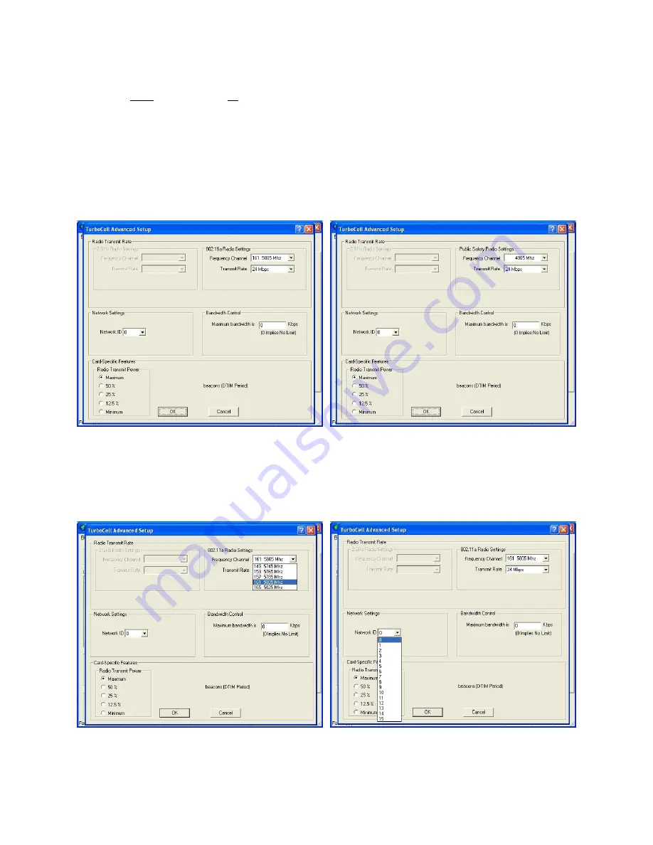
button. The
TurboCell Advanced Setup
screen appears. Notice that this screen
is slightly different depending on whether you are configuring a 5.8 GHz radio (Figure 3.6a) or a
4.9 GHz radio (Figure 3.6b)
Figure 3.6a – TurboCell Advanced Setup Screen Figure 3.6b – TurboCell Advanced Setup Screen
for 5.8 GHz Radios
for 4.9 GHz Radios
10. Select a Frequency Channel from the pull down menu box. Both units in a link must be configured
with the same frequency value. Figure 3.7 shows the screen for a 5.8 GHz radio. There is only one
possible frequency for 4.9 GHz radios (4.965 GHz).
Figure 3.7 – TurboCell Advanced Setup Screen
Figure 3.8 – TurboCell Advanced Setup Screen
for 5.8 GHz Radios – Frequency
for 5.8 GHz Radios – Network ID
11. The Marquee P-MP is optimized for a transmit rate of 24 Mbps and the transmit power is preset from
factory with the proper value.
Version 1.3(a)
Page 18
Jul 2005


