Telestream PRISM MPI2-10 User Manual Download Page 92

Configure the Instrument

Configure and Select Signal Inputs

PRISM MPI2-10-MPX2-10 User Manual

94

Note:

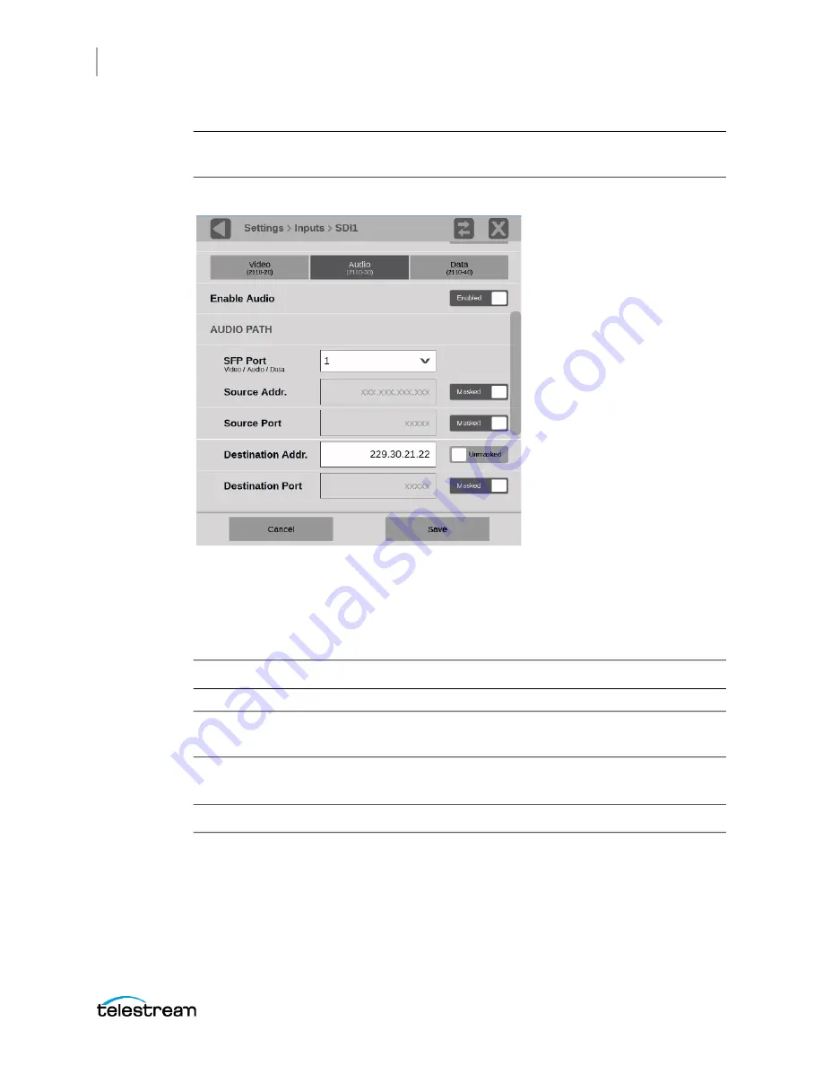
To decode Audio (2110-30) stream, it’s necessary for Video (2110-20) to be 

available and subscribed.

a.

Select the 

Audio 

tab.


b.

Move the Enable Audio slider to 

Enabled

 so the audio stream is subscribed from 

the media switch.

c.

Select the number in SFP Port.

d.

Enter the Source and Destination information for each audio stream.

Note:

The SFP (physical) Port configuration is common for Video, Audio, and Data.

Note:

The Source Addr, Source Port, and Destination Port are optional if the IP stream 

is uniquely specified.

e.

Set the RTP Payload Type


between 96 and  127.

Note:

The RTP Payload Type is displayed in the IP Status application.

f.

Set the number of channels in the audio stream between 2 and 16.
The number of channels must be an even number (2, 4, 6, etc.). A maximum of 16 

audio channels, across all audio streams, are supported.

Summary of Contents for PRISM MPI2-10

Page 1: ...PRISM MPI2 10 and MPX2 10 SDI IP Waveform Monitor User Manual April 2021 D00010021C...

Page 2: ...ew performance All replaced parts modules and products become the property of Telestream In order to obtain service under this warranty Customer must notify Telestream of the defect before the expirat...

Page 3: ...ODED OR INCORPORATED WITHIN EQUIPMENT CONTACT THE NEAREST TELESTREAM SALES OFFICE DEFINITIONS Telestream meansTelestream LLC a Delaware limited liability company and its Affiliates or the local Telest...

Page 4: ...ained a respective licensing right Customer shall pay when due all property taxes that may now or hereafter be imposed levied or assessed with respect to the possession or use of the Program or this l...

Page 5: ...RAM EVEN IF TELESTREAM OR SUCH OTHERS HAS ADVANCE NOTICE OF THE POSSIBILITY OF SUCH DAMAGES THIRD PARTY DISCLAIMER Except as expressly agreed otherwise third parties from whom Telestream may have obta...

Page 6: ...6 PRISM MPI2 10 MPX2 10 User Manual...

Page 7: ...Operation 62 External Touchscreen Display Operation 64 Manage Tile Display 65 Remote Control through VNC Operation 68 Remote Control through API Commands 71 Configure the Instrument 77 Configure and S...

Page 8: ...P Graphs Application 226 PIT Histogram Application 232 PTP Graphs Application 235 Stream Timing Application 238 IP Generator Application 244 SDI Generator Application 251 Datalist Application 254 ANC...

Page 9: ...articular installation Operation of this equipment in a residential area is likely to cause harmful interference in which case the user will be required to correct the interference at his own expense...

Page 10: ...cal Equipment for Measurement Control and Laboratory Use Part 1 General Requirements S curit CAN CSA 22 2 NO 61010 1 12 Gil Gl2 Exigences de s curit pour l lectricit Mat riel de mesure de contr le et...

Page 11: ...it de Classe A Dans un environnement domestique ce produit risque de creer des interferences radioelectriques ii appartiendra alors a l utilisateur de prendre les mesures specifiques appropriees Notes...

Page 12: ...r product Battery Recycling This product may contain a rechargeable battery which must be recycled or disposed of properly Please properly dispose of or recycle the battery according to local governme...

Page 13: ...ollowing safety precautions to avoid injury and prevent damage to this product or any products connected to it Carefully read all instructions Retain these instructions for future reference Comply wit...

Page 14: ...minal ratings To avoid fire or shock hazard observe all rating and markings on the product Consult the product manual for further ratings information before making connections to the product Do not ap...

Page 15: ...afety summary and the General safety summary before performing any service procedures To avoid electric shock Do not touch exposed connections Do not service alone Do not perform internal service or a...

Page 16: ...for future reference Comply with local and national safety codes For correct and safe operation of the product it is essential that you follow generally accepted safety procedures in addition to the s...

Page 17: ...ower cord be connected to the instrument before the power cord is connected to the AC power source Caution To prevent data loss we strongly recommend you first shut down the instrument before disconne...

Page 18: ...ation for the PRISM SDI IP Waveform Monitor Product documentation Document Manual type Part number Description User Manual Primary User D00010021x Provides detailed operating information Release Notes...

Page 19: ...9 equipment rack PRISM MPI2 RACK MD Installation and Safety Instructions Field Install Instructions 071 3728 00x Provides installation and safety information for the PRISM MPI2 RACK MD Rack Cabinet wi...

Page 20: ...lestream Web site for your regional authorized Telestream distributor Telestream Technical Writers Email techwriter telestream net If you have comments or suggestions about improving this document or...

Page 21: ...your instrument and provides a list of key features Controls and connectors shows you how to verify that you have received all of the parts of your instrument and provides a list of standard and optio...

Page 22: ...DI IP signal paths PRISM is an ideal solution for monitoring SDI IP hybrid environments including master control rooms production studios OB vans and signal contribution distribution centers PRISM Mod...

Page 23: ...serve issues that may cause intermittent loss of video audio or data Monitor PTP trend graphs to ensure proper IP system setup for robust sync system Telestream patented Timing display the SDI versus...

Page 24: ...12G SDI physical layer measurements to check SDI signal quality and integrity optional On screen tools for accessing frequently used settings without opening a separate menu Audio volume and balance...

Page 25: ...MP2 FMT 4K 12G SDI 3840x2160 4 2 2 YCbCr 10b 50 59 94 60p MP2 FMT 4K Quad Link 12G SDI 7680x4320 4 2 2 YCbCr 10b 50 59 94 60p MP2 FMT 8K Supported SDI formats Supported video formats in SMPTE 2110 20...

Page 26: ...cludes Datalist CC decode and ANC Session MP2 PROD adds a node locked license for production feature sets this includes Stop False Color Light meter HDR WCG Conversion CIE and HDR Measurements Support...

Page 27: ...description 29 PRISM MPI2 10 MPX2 10 User Manual MP2 GEN adds a node locked license for SDI IP signal generator this includes IP SDI Generator application MP2 EXTNDSP adds a node locked license for en...

Page 28: ...e cabinet front panel has two USB ports and a headphone port for one MPI unit Dual Rack Cabinet Versions There are two versions of the instructions for the MPI RACK MM and MPI RACK MW dual rack cabine...

Page 29: ...ISM MPI2 monitor not included next to an external HD display in a 3RU full width rack A software license is required to enable the extended display feature For information on how to install and use th...

Page 30: ...power source Connect the power cord to the power connector on the rear panel of the instrument The power connector is keyed to be directional with the flat portion of the power cord housing facing th...

Page 31: ...on the cable You must pull on the connector housing to disengage the locking mechanism To minimize the risk of damage to the instrument it is strongly recommended that the power cord be disconnected...

Page 32: ...turn the instrument off Or in the instrument a Select Settings b Select Utilities c Select Power d Select Power Down Now Caution To prevent data loss we strongly recommend you first shut down the ins...

Page 33: ...r source Connect the power cord to the power connector on the rear panel of the instrument The power connector is keyed to be directional with the flat portion of the power cord housing facing the lef...

Page 34: ...Standby button turns red during the power on sequence and turns green and remains green in normal operation MPX2 10 Power off Procedure 1 Press the Power Standby button on the instrument front panel t...

Page 35: ...10GE signals If the SFP module does not match the unit signal setting for example a 25GE SFP module is installed the Link Status in Network under Settings returns SFP Error To remove the SFP module pu...

Page 36: ...Set up the instrument as described in this procedure Choose Manual IP mode to set the IP address manually Be sure to set an address that is compatible with the setting of your PC Note The default IP a...

Page 37: ...the Manual submenu to set the IP address subnet mask gateway address DNS address and DNS Search Domain parameters you obtained from your LAN administrator Be sure to use compatible addresses between t...

Page 38: ...ignals SDI inputs 2 and 4 support SD HD 3G signals Single SDI link Option MP2 FMT 4K is required for 12G support When used as a single link only one of the SDI 1 4 inputs is active at a time Eye diagr...

Page 39: ...IN 9 Connector for an AC power source 10 DP Two Display Port outputs are for external monitors The output video format is 1920 1080 1 Note An MPI2 10 can use a maximum of 1 external display DP or HDM...

Page 40: ...uture use 1 When connecting to an external monitor a monitor with a 1920 1080 capable display works best with the instrument 2 Audio output is an 1 8 inch 3 5mm diameter port for a headset It has conn...

Page 41: ...1 Connector for an AC power source 2 DP Two DisplayPort outputs are for external monitors The output video format is 1920 1080 1 Note An MPX2 10 can use a maximum of 2 external displays DP or HDMI 3...

Page 42: ...ions MP2 FMT 4K and MPX2 10 PHY Quad 4K links when used in conjunction with the SDI 1 4 inputs Option MP2 FMT 4K only When used as Quad 4K links all four SDI inputs are active 10 PPS PPS connector out...

Page 43: ...mum of 2 external displays DP or HDMI 1 When connecting to an external monitor a monitor with a 1920 1080 capable display works best with the instrument 2 2 Audio output is an 1 8 inch 3 5mm diameter...

Page 44: ...Item number Description 1 4 Application tiles 1 41 5 Status bar The left side of the Status bar has icons with links to various instrument settings including Volume Presets Settings Input type and the...

Page 45: ...rom the instrument remove the power cord Caution To prevent data loss we strongly recommend you first shut down the instrument before disconnecting the power cord Press Power Standby or select Setting...

Page 46: ...ctivity icon indicates the number of messages waiting in and devices connected to the instrument 1 Select the Activity icon to view the DASHBOARD messages which includes devices connected to the instr...

Page 47: ...nu The Activity icon is color coded A gray icon means no alarms have been activated A yellow icon means at least one alarm is active but it is not longer present A red icon means at least one alarm is...

Page 48: ...re are both active and cleared alarms in the group the button is red The alarm titles below the group buttons color coding A white title means the alarm is not turned on in the DASHBOARD A green title...

Page 49: ...rn on a group or groups of alarms in the DASHBOARD select the checkbox of any alarm group To turn an alarm off clear the checkbox To turn on any specific alarm or alarms select the title of a group of...

Page 50: ...methods in the Activity DASHBOARD To acknowledge all of the alarms in the DASHBOARD at the top of the DASHBOARD select Acknowledge Alarms All the alarms and all the group buttons are set to green unl...

Page 51: ...tc The alarm group is circled in white and the alarms in that group appear below the group buttons To see the alarms in the Event Log application Select View in tile 1 at the top of the DASHBOARD The...

Page 52: ...Getting Started Activity Center PRISM MPI2 10 MPX2 10 User Manual 54...

Page 53: ...ction describes the primary methods of operating the instrument MPI2 10 front panel touchscreen MPX2 10 front panel controls External touchscreen display Keyboard and mouse Remote control using VNC Re...

Page 54: ...een a half screen tile and a full screen display of the selected application Double tap a full screen display to return to the quarter or half screen tile Swipe up or down or left or right as necessar...

Page 55: ...ons in the All Applications menu can vary depending on what options the user has ordered Change the Applications in the Application Toolbar 1 In the All Applications menu select Edit from the menu hea...

Page 56: ...color of the application icons on or off this includes the applications in the All Applications menu and the Applications menu In the All Applications menu header select Border Color to pull down the...

Page 57: ...d have buttons on the top and bottom of the display that allow you to adjust the application settings When first selecting one of the displays a highlighted ring appears around each available on scree...

Page 58: ...nd rear panel headphone and optional speaker outputs Push the BALANCE control to re center the balance 1 3 PRESET button Press one time to prepare the instrument for a preset selection from preset Gro...

Page 59: ...you want to recall 1 6 Note When you use the PRESET and INPUT buttons the associated menus appear on the display The menus close after a short time out period Similarly when you use the VOLUME control...

Page 60: ...keyboard is mapped to function as the Home icon which closes any displayed menus Volume Control If your keyboard has volume control keys you can use them to control the volume of the audio output on...

Page 61: ...t a preset from another Preset Group B F For example press ALT and at the same time and press p three times to make a selection from Preset Group C 2 Press a number from 1 to 6 to select the input or...

Page 62: ...ol the instrument Two connections are required Connect the Display Port output from the PRISM monitor to the input on the external device Connect the output of the external device to one of the USB po...

Page 63: ...on your requirements The default for the PRISM instrument is to display four quarter screen tiles These configurations show how to expand the applications to half or full screen tiles and collapse the...

Page 64: ...the quarter screen icon or the full screen icon to change between views Quarter screen Tiles Sizing tiles to a quarter screen allows you the flexibility to view up to four tiles at the same time There...

Page 65: ...isplay 67 PRISM MPI2 10 MPX2 10 User Manual To extend a tile vertically half screen mode In the application toolbar select the expand icon to expand the tile vertically Select the compress icon to col...

Page 66: ...ress of the instrument 3 On your computer open your VNC client and enter the IP address from the Control IP Port of the instrument in the VNC Server search bar The VNC client connects to the instrumen...

Page 67: ...isplays 4 In the Control bar select the Settings icon to open the Settings menu 5 In the Settings menu use the Scaling Mode drop down list to select Local Scaling and then select Apply 6 In the Contro...

Page 68: ...ettings in the Network menu open the WEB REMOTE tab The webbrowser connects to the instrument with the browser display appearing exactly like the display on the external monitor but with a slower upda...

Page 69: ...ut Access the API Documentation 1 Find the PRISM hostname on the Status bar under the Telestream logo next to the Activity icon Or find the IP address select Settings then Network and under CONTROL IP...

Page 70: ...through API Commands PRISM MPI2 10 MPX2 10 User Manual 72 Syslog PRISM supports Syslog protocol RFC 5424 for alarms and events Setup Syslog 1 Select the Settings icon to open the Settings menu 2 sele...

Page 71: ...B is provided in the file prism_mon mib file which can be downloaded from the PRISM web page SNMP trap destination address is set with RESTful API using post operation through Postman or a similar app...

Page 72: ...NMP_TRAP_ENABLE_ON c Execute as a POST operation 3 Set the trap destination address a Enter command xxx xxx xxx xxx api snmp_trap_destination_address b In the body of the JSON command enter string yyy...

Page 73: ...manager on the machine where you want to check the traps a From the SNMP manager configure the SNMP agent PRISM IP address b Load the prism mib file c Open the trap receiver window d Confirm the trap...

Page 74: ...Methods of Operation Remote Control through API Commands PRISM MPI2 10 MPX2 10 User Manual 76...

Page 75: ...Configure and Select Signal Inputs HDR monitoring Configure Instrument for HDR WCG Monitoring PTP reference settings Configure Reference Settings Presets Set and Recall Instrument Presets Internal ti...

Page 76: ...ed in the middle of the status bar The first line is the user defined name and the second line is the format Caution IGMP communications can fail when the Video IP Ports are configured for the same IP...

Page 77: ...n and select one of the four physical SDI inputs to monitor Select Video Settings These settings are the same for Single and Quad Link input configurations The Gamma and Color Gamut settings define th...

Page 78: ...e drop down menu Auto The system selects the correct setting based on the information in the incoming signal 525I 625I 720P 1080I 1080PsF 1080P 2160P 3 If a 3 gigabit transport is being used select th...

Page 79: ...representation for 0 black and 100 white respectively PQ Narrow The reference OETF with a high luminance range capability of 0 to 10 000 cd m2 standardized in SMPTE2084 The EOTF is the inverse of OET...

Page 80: ...s not present Rec 709 is selected Rec 709 Standard for HD Rec 2020 Standard for 4K Note Rec 709 gamut is automatically selected when the SD format is detected selected in the video signal Select Audio...

Page 81: ...ser Manual 2 Choose the type of audio Select PCM or Select DOLBY use of Dolby requires the MP2 DLBY license Select PCM a Select Program Configuration b Move the Program Configuration slider to On c Se...

Page 82: ...luding the default e Select Save and close the menu Note You must save the program configuration to update the programs in the audio bars and loudness meter Select DOLBY Note Dolby D Plus and E are av...

Page 83: ...option MP2 FMT 4K is present 6 Use the UHD 4K Mode buttons to select Auto Sq Div Square Division or 2 SI Two Sample Interleave 7 Select Video Settings 8 Select Audio Settings Note In AUTO mode the ins...

Page 84: ...using the text editor Enter a name with a maximum of 16 characters Select the Clear icon next to the input box to remove the existing name Use the shift key to access capital letters Use the backspace...

Page 85: ...reconstructed output stream is created from the two input streams The reconstructed stream is used downstream for various display tiles like Picture The buffer size to absorb the packet reception tim...

Page 86: ...Enter 11 Scroll down to enter the Source and Destination information for Path 2 Select Video Settings The Gamma and Color Gamut settings are the same for ST2022 6 and ST2110 video stream configuratio...

Page 87: ...l Transfer Function is the inverse of OETF The narrow Scaling places the extremes of the nonlinear color value from zero to unity at code words 40 hex 64 dec and 3AC hex 940 dec in a 10bit representat...

Page 88: ...2 10 MPX2 10 User Manual 90 Note Rec 709 gamut is automatically selected when the SD format is detected or selected in the video signal Select Audio Settings 1 Select AUDIO 2 Choose the type of audio...

Page 89: ...it Repeat until all the audio in the current input signal have programs assigned to channels M is mono 1 channel ST is stereo 2 channels 5 1 is surround sound 6 channels 7 1 is surround sound 8 chann...

Page 90: ...ically set up based on the Dolby D D Plus E metadata 3 Tobegin monitoring this input select the configured input See Select Input Configure and Monitor ST2110 1 Select the Settings icon to open the Se...

Page 91: ...o slider to Enabled to begin configuration c Enter the information in SFP Port Source Addr Source Port Destination Addr and Destination Port for each video stream d Set the RTP Payload Type between 96...

Page 92: ...nter the Source and Destination information for each audio stream Note The SFP physical Port configuration is common for Video Audio and Data Note The Source Addr Source Port and Destination Port are...

Page 93: ...and Select Signal Inputs 95 PRISM MPI2 10 MPX2 10 User Manual Note The Bit Depth is already set to 24 g Select Save Select Audio Settings 1 Choose the type of audio Select PCM or Select DOLBY use of D...

Page 94: ...it Repeat until all the audio in the current input signal have programs assigned to channels M is mono 1 channel ST is stereo 2 channels 5 1 is surround sound 6 channels 7 1 is surround sound 8 chann...

Page 95: ...bars in the Audio application and to monitor with headphones When all the channels are unassigned all the channels are treated as stereo pairs The audio programs in the Dolby E stream are automaticall...

Page 96: ...nd Destination Port for each data stream d Set the RTP Payload Type between 96 and 127 Note The RTP Payload Type number must be unique for each IP stream The RTP Payload Type is displayed in the IP St...

Page 97: ...the RTP Payload Type between 0 to 127 5 Select the Video Format and corresponding Frame Rate 6 Select Save and close the menu 7 Tobegin monitoring this input select the configured input See Select Inp...

Page 98: ...the graticule that fits your application The trace represents the video data in the vertical axis See Waveform Application The mV and Code Value are fixed graticules They are compatible with the tradi...

Page 99: ...sed for mastering the content for a targeted HDR system Transfer Function Color Space Conversion Option MP2 PROD only Transfer function color space conversion is available in Waveform Vector Diamond a...

Page 100: ...ent 1 Select the Settings icon to open the Settings menu 2 Select Network to open the Network submenu 3 Slide the Enable NMOS Discovery Registration control to Enabled or Disabled 4 Close the Network...

Page 101: ...S on your instrument 1 Select the Settings icon to open the Settings menu 2 Select Network to open the Network submenu 3 Slide the Enable NMOS Discovery Registration control to Enabled or Disabled 4 C...

Page 102: ...alues associated with audio loudness measurements This instrument maintains a running audio loudness session Turn on the Loudness Display 1 Open the Audio app 2 In the application toolbar select the T...

Page 103: ...oudness Display Parameter Available Configurations Remarks LOUDNESS METERING MODE BS 1770 1 with DI1 BS 1770 2 with DI Leq A with DI BS 1770 2 w o DI Modes implies a weighting function A weighting or...

Page 104: ...of the level bars green letters mean it is selected and the Loudness meter measures the levels based on that audio program Note Changing the selected Audio program that the Loudness meter measures cha...

Page 105: ...the loudness calculations Loudness Meter Labels The labels at the bottom of the audio bars marked as 1 in this example means it is program 2 and there is a left and a right channel The label at the bo...

Page 106: ...the LFE is muted The surround signal is added 180 degrees out of phase to the left and center signal making up the left total channel The surround signal is added in phase 0 degrees to the right and...

Page 107: ...Mode Select Off Line or RF Line and RF are modes of Dynamic Range Control DRC compression factors that are applied when decoding Dolby content for monitoring or output Select Downmix Dynamic Rng Selec...

Page 108: ...s icon to open the Settings menu 2 Select Outputs to open the Outputs submenu 3 Set the SDI output to Loop through or Generator 4 Close the Outputs menu SDI OUT loop through of IP inputs is available...

Page 109: ...de on the Status bar ANC LTC linear time code ANC VITC vertical interval time code and Date Readout are supported 1 Select the Settings icon to open the Settings menu 2 Select Anc Data to open the Anc...

Page 110: ...d IP timing against PTP To choose the external reference 1 Select the Settings icon to open the Settings menu 2 Select Reference to open the Reference submenu 3 Select one of the reference options Int...

Page 111: ...ate Input The REF input is terminated at the REF input BNC There is no signal at REF output BNC Configure the PTP Reference Settings 1 Select the Settings icon to open the Settings menu 2 Select Refer...

Page 112: ...Sync messages are sent as Multicast However the Delay request and Delay Response messages are sent as Unicast 6 Select the Domain 0 127 box to open the editing display 7 Use the editing controls to e...

Page 113: ...6 B1 B6 C1 C6 D1 D6 E1 E6 and F1 F6 All instrument settings except those set in the Utilities and Network Settings submenus of the Configuration menu are saved in a Preset Settings that are not saved...

Page 114: ...a named preset with new name and settings 1 Set up the instrument exactly as you want it configured This includes selecting the application display for each tile and configuring inputs and the PTP ref...

Page 115: ...use the keyboard If you do not want to change the name select Save A confirmation window displays 8 Select OK to save the preset The preset name changes from empty or a name to the entered name The nu...

Page 116: ...e Presets Rename submenu 4 Select the Preset group at the top of the submenu to select the group with the preset to rename this includes naming an empty preset 5 Select the name box of the preset you...

Page 117: ...name the preset just as in the Presets Rename submenu Download and Upload PRISM Presets To download the presets of an entire PRISM clone the presets and upload them to another PRISM there are two meth...

Page 118: ...s and then select COPY FROM USB 5 Select the USB memory drive and select Copy The downloaded presets are uploaded to the PRISM 6 Select the Activity icon and then select the Eject icon to unmount the...

Page 119: ...rename the presets file 4 To upload the presets to another PRISM go to Upload the Presets through the PRISM Homepage Upload the Presets through the PRISM Homepage Caution This overwrites all existing...

Page 120: ...ntent empty is displayed on the preset button 3 Select the preset button to recall The selected preset button is highlighted and the instrument settings change to those assigned to the selected preset...

Page 121: ...ttings icon to open the Settings menu 2 Select Presets to open the Presets submenu 3 Select Recall Factory Preset A confirmation box displays 4 Select OK to confirm the selection and to reset the inst...

Page 122: ...put name Input type Input connector SDI In 1 SDI SDI 1 SDI In 2 input configuration Input name Input type Input connector SDI In 2 SDI SDI 2 SDI In 3 input configuration Input name Input type Input co...

Page 123: ...definable thresholds to set specific limits for the alarm Configure Alarms Open the Alarms Select Settings and then select Alarms To turn on the group of alarms select the checkbox under Dashboard for...

Page 124: ...he reset icon under Threshold for the group Select a Specific Alarm 1 Select the alarm group that contains the specific alarm 2 Select the UI checkbox of the alarm to monitor Note If the alarm shows i...

Page 125: ...ge for a time longer than the duration setting Audio Signal Lost No Audio is present in the currently active signal CC Closed Captions Subtitles CEA708 Closed Captions Lost No valid CEA708 closed capt...

Page 126: ...ace Ethernet Buffer Overflow Overflow was detected on IP Video Ports Ethernet CRC Error CRC error was detected in an Ethernet frame Ethernet Interface Saturated Ethernet interface is saturated HBRMT H...

Page 127: ...l embedded CRC Cyclical Redundancy Check that was calculated for the video signal Using a known test signal the CRC status can be used to verify integrity through a system An error means that the C Ch...

Page 128: ...ssion error has occurred SMPTE 352M Payload ID Missing A mandatory SMPTE352M video payload identifier packet is missing Video Format Changed TRS count performed by the instrument does not agree with t...

Page 129: ...e Display settings menu To adjust graticule and trace intensity 1 Select the Settings icon to open the Settings menu 2 Select Display to open the Display submenu 3 Use the plus icon to increase intens...

Page 130: ...nu 3 Select Time and Date to open the submenu The submenu has two tabs TIME ZONE and TIME AND DATE Caution Excess time changes can cause the loss of all license files If the instrument license files a...

Page 131: ...a 24 hour clock so no AM PM setting is required 8 When you are done setting the time and date select Save 9 The message box displays and asks whether you want to reboot the instrument now or later to...

Page 132: ...website a Use a web browser and go to the Telestream website software page www telestream net video resources htm Software b Click the product and model title that best matches your instrument such a...

Page 133: ...irmware release 2 Insert the USB memory device into a USB port on the PRISM monitor 3 On the PRISM monitor select the Settings icon to open the Settings menu 4 Select Utilities to open the Utilities s...

Page 134: ...from the instrument 10 Remove the USB device from the PRISM monitor 11 Shut off the instrument a Select Settings b Select Utilities c Select Power d Select Power Down Now 12 Press the Power Standby bu...

Page 135: ...PRISM instrument to a local network and turn on power 2 After the instrument has booted find the IP address select Settings then Network and finally select the STATUS tab 3 Copy the IP address of the...

Page 136: ...trument needs service you may be asked to provide the diagnostics file to Telestream to aid in troubleshooting problems with the instrument 1 Select the Settings icon to open the Settings menu 2 Selec...

Page 137: ...ctions 139 PRISM MPI2 10 MPX2 10 User Manual Functions This section describes additional functions available on the PRISM monitor Headphone and speaker volume balance and source adjustment Stream Capt...

Page 138: ...slider or arrow buttons to turn the volume up or down Use the slider or arrow buttons to adjust the audio balance left or right Select the mute button to mute the audio Select the downmix button to l...

Page 139: ...udio ports or USB inputs or the internal speakers on MPX2 10 requires option SPKR The name of the audio device in the list depends on what port is used and the device itself Speakers MPX2 10 integrate...

Page 140: ...USB 3 0 drive connected to the rear panel of the PRISM monitor Note For the fastest capture rate with the Stream Capture we recommend using a USB 3 0 drive plugged into one of the USB 3 0 ports on th...

Page 141: ...menu select Capture Note If the Capture configuration menu does not appear under the Settings menu option MP2 IP MEAS is not installed and stream captures are disabled 4 Select Screenshot and Stream u...

Page 142: ...ed under the Capture icon Note During capture the Aux Out signal is turned off and Pictures and Traces are blanked Note Select the Capture icon again to stop the stream capture early The Capture icon...

Page 143: ...ch ofthese applicationscanbe viewed in quarter screen half screen or full screen mode double tap in the application to change between modes To see the All Application menu select the Tiles icon and th...

Page 144: ...d Channel Correlation meter for monitoring two channel audio phase Lissajous Channel Correlation and Audio Session require Option MP2 AUD Also included are Test level and Peak program level indicators...

Page 145: ...e parameters of the IP stream including total bit rate session bit rate PIT RTP sequence errors video CRC errors and TS DF Time Stamped Delay Factor PIT Histogram Application Use this to view a histog...

Page 146: ...Description IP Generator Application Use this to provide an IP test signal to check the receiver device and signal path SDI Generator Application Use this to provide an SDI test signal to check the re...

Page 147: ...scription Jitter Application Use this to display the wave shape of the jitter and allows you to view additional time domain information Eye Application Use this to view an eye pattern diagram of the S...

Page 148: ...Toview options installed on the instrument select Settings then Utilities and then Options Status Indicators Many of the application displays include status icons which provide a quick method for view...

Page 149: ...e Waveform display is a signal level versus time display of the video signal Waveform Settings Menu Note The Move icon is in the settings menu header Select this icon to move the settings left of righ...

Page 150: ...between the lines or fields The available sweep options depend on which display style is active When the Parade display style is active you can select from 1 line or 1 field When Overlay display style...

Page 151: ...splays to convert the Gamma and Color Gamut settings for the signal to SDR Narrow and BT 709 requires Option MP2 PROD Note Conversion to Rec 709 automatically converts to BT 709 otherwise the graticul...

Page 152: ...screen tools Select the tool button for the setting you want to adjust All the available tools are located on the top and bottom of the display and are highlighted for a few seconds when the applicati...

Page 153: ...a range of 0 25x to 2 00x gain 2 0x has a range of 0 50x to 4 00x gain 5 0x has a range of 1 25x to 10 00x gain 10 0x has a range of 2 50x to 20 00x gain To adjust the gain On a touchscreen use a pin...

Page 154: ...f the horizontal trace Select and drag to move the trace on the touchscreen This method can be performed without using the button Use a mouse scroll wheel to move the trace For incremental adjustments...

Page 155: ...ertical trace Select and drag to move the trace on the touchscreen This method can be performed without using the button Use a mouse scroll wheel to move the trace For incremental adjustments use the...

Page 156: ...ta are displayed on the right side of the application Note The cursor tab provides an easy way to adjust each cursor 5 Change the V button to On to display two voltage cursors 6 Select the V Units but...

Page 157: ...left corner of the application to expand the available display options 2 Select one of the display options 3 Filter each option by the individual waveforms to display Select YPbPr to display any combi...

Page 158: ...play format options 2 Select the Mag option to select from the magnification options of Best View x1 x10 x20 x25 or x50 3 Select the Display Style option to switch between Parade or Overlay 4 Select t...

Page 159: ...on at the bottom of the tile 2 Select 1 Line To scroll through lines select the or buttons To enter a specific line to monitor select Line Sel and enter the line on the keypad or in the Picture applic...

Page 160: ...ster line the SDI Line is the selected line including vertical blanking the link number appears below the SDI Line Note In link the letters A B C or D refers to the physical links The numbers 1 2 3 or...

Page 161: ...ITU R BT 709 or 2020 color space With Option MP2 PROD transfer function color space conversion allows for an ITU R BT 709 color space to verify wide color gamut compatibility Vector Settings Menu Ope...

Page 162: ...ed See Configure Instrument for HDR WCG Monitoring Convert to Rec 709 mode is not supported for SD signals Line Select Line Select allows you to choose the picture lines to monitor in the display Eith...

Page 163: ...for a few seconds when the application is first opened or if you select anywhere in the middle of the application tile Gain Increase or decrease the magnification of the trace display 1 Select Gain to...

Page 164: ...factor you select 1 0x has a range of 0 25x to 2 00x gain 2 0x has a range of 0 50x to 4 00x gain 5 0x has a range of 1 25x to 10 00x gain 10 0x has a range of 2 50x to 20 00x gain Use these methods...

Page 165: ...os button to allow adjustment of the horizontal trace Select and drag to move the trace on the touchscreen This method can be performed without using the button Use a mouse scroll wheel to move the tr...

Page 166: ...eset icon to reset the vertical position adjustment to default Bar Targets Change the scaling of the Vector display 1 Select the Bars button in the bottom right corner of the application to expand the...

Page 167: ...d or in the Picture application use the line select cursor for active lines Depending on the resolution in the signal the Line Select provides different information If a signal is SD HD 3G the Line nu...

Page 168: ...ted raster line the SDI Line is the selected line including vertical blanking the link number appears below the SDI Line Note In link the letters A D refers to the physical links The numbers 1 4 refer...

Page 169: ...ion displays show audio phase information Dolby E decoding can be performed on a specified SDI input channel pair Note The Lissajous Channel Correlation meter and Audio Session displays require softwa...

Page 170: ...Lissajous Display The Lissajous display is a visual of a user specified pairing of channel inputs with a channel correlation meter To turn on the Lissajous display in the Audio Settings in Aux Displa...

Page 171: ...evel meter dynamic response Go to Audio in the global Settings menu to change the ballistics Level Meters Level meters are vertical bar graphs The height of the bar indicates the amplitude of the audi...

Page 172: ...highly correlated signals the indicator is green and moves to the right towards 1 For uncorrelated signals the indicator is yellow and tends to stay in the middle around 0 For anti correlated signals...

Page 173: ...hannel CLIP Indicates the number of times the audio level was at the digital code for the maximum amplitude for ten consecutive samples OVER Indicates the number of times the audio level exceeded 0dB...

Page 174: ...ypically used for aligning audio levels Total Volume Indicator the cyan polygon formed by connecting the level indicator end points showing the total sound volume of the L R Ls and Rs channels Each co...

Page 175: ...he same signal level the white tic mark on the bar appears directly above the C level indicator The white tic mark moves right or left depending on the relative balance between the three channels A sh...

Page 176: ...d sound program with weak center channel presence Example 6 Monaural signal in channels Ls and Rs creating a phantom source in the center as in a 3 1 surround sound system Loudness Meter It is a part...

Page 177: ...ser Manual To turn on the audio loudness values in the Audio Settings in Aux Display set Loudness Meter to On The Loudness Meter appears to the right of the Audio bars Audio Session It consists of sev...

Page 178: ...Audio Settings set Audio Session to On The Audio Session appears below the audio bars Downmix Solo It allows you to select any one channel of a downmixed 5 1 or 7 1 stream and listen to it alone This...

Page 179: ...us bar to open the volume controls 4 In the volume controls select the downmix button 5 Select the Home icon to close the volume controls 6 Select a channel to isolate in the Audio application To chan...

Page 180: ...u see the picture generated by the video signal Copyright 2008 Blender Foundation www bigbuckbunny org Picture Settings Menu Note The Move icon is in the settings menu header Select this icon to move...

Page 181: ...imation may cause some artifacts Format Overlay Set to On to display the format information on top of the picture Select and drag the format information window to set the location Source ID Overlay Pr...

Page 182: ...re Measurements for more information about this feature Measurement Thresholds Threshold for the HDR picture measurements are made in this menu See Picture Measurements for more information about this...

Page 183: ...put CEA 608 A standard format of closed captions subtitles data used in the U S Canada and Mexico for analog TV transmissions If a service has no activity for 10 seconds it is considered missing In th...

Page 184: ...Overlay to On This turns on the measurements overlay in the Picture application After it is visible the overlay window can be dragged to any location in the Picture tile Select the picture measurement...

Page 185: ...is threshold in Nits is considered in the HDR zone Area percent Defines the brightest percentage of the picture used to determine the bright threshold in Nits Brightest Area percent Defines the bright...

Page 186: ...e and a 20x20 pixel area in a 7680x4320 picture Turn on or Change the Lightmeters 1 Open the Picture Settings menu and select Lightmeter 2 Set the Lightmeter Overlay to On 3 Select the number of neede...

Page 187: ...range Copyright 2008 Blender Foundation www bigbuckbunny org The false color ranges are defined in nits or stops depending on the gamma curve set up in the input select Settings and then Input If a ca...

Page 188: ...the readout in the table header Specific colors can be displayed by selecting the check box in the Enable column of the table You can change the Nits or Stops range even if the check box is not set T...

Page 189: ...rovide a quick view of the status of the parameters contained in each tab SDI FORMAT Use this tab to view the status of various SDI signal parameters on the input signal VPID 352 Use this tab to view...

Page 190: ...icates whether an End of Active Video Placement error has occurred Field Length Err Indicates whether a Field Length error has occurred Line Length Err Indicates whether a Line Length error has occurr...

Page 191: ...ce of a SMPTE 352M payload The number of data streams determines the number of links with the VPID values shown in hex You may select a link to display the decoded VPID information in the right pane R...

Page 192: ...match the calculated CRC value which indicates that a transmission error has occurred C Chan CRC Error Displays the status of the C channel embedded CRC Cyclical Redundancy Check that was calculated...

Page 193: ...f the associated error OK No error is currently detected Invalid The data for the item is currently invalid Missing The data for the item is currently missing Error The associated error is currently i...

Page 194: ...sition of the horizontal and vertical sync pulses are compared to the input signal In the case of PTP the current time is obtained and compared to the SMPTE Epoch When an input is configured for ST202...

Page 195: ...he circle represents the timing of the input signal A signal that is early is above or to the left of the cross hair A signal that is late is below or to the right Offsets The difference in timing bet...

Page 196: ...ows both absolute time and the time parsed into lines or horizontal delay as time and pixels For ST2110 20 streams the Timing application displays the time of the first packet of the frame Since ST211...

Page 197: ...icon Select the Reset icon to hide all log items so only new log items are displayed Select Undo Reset in the settings menu to show the log items that were hidden by pressing Reset Track icon The Trac...

Page 198: ...entary error that was in error condition but is now in normal condition The PTP or TC field is blank when the selected time source is not available White items are informational and identify a change...

Page 199: ...s menu in Anc Data in Timecode Format Select PTP to set PTP UTC for error tracking in the Event Log Undo Event Log Reset Select Undo Reset to cancel the last reset of the logged events Filter Event Lo...

Page 200: ...ups The Event Log immediately adds or removes errors from the list If all groups are selected no filter the Group filter icon is empty If any group is not selected a filter is applied the Group filter...

Page 201: ...ll checkboxes to see all errors or unselect all to hide all errors select All Events The Event Log immediately adds or removes errors from the list If all groups are selected no filter the filter icon...

Page 202: ...y a filled filter icon next to a tile it limits what any other filter shows For example if no groups are selected in the Group filter then no errors appear even if all the events are selected To move...

Page 203: ...tion time are not required To enter a filter time Select in the Time From field and either enter a time hh mm ss with a keyboard or select the time using the on screen Adjust Time tool and select Ente...

Page 204: ...in the Duration field and enter hours with a keyboard or use the on screen keypad and select Enter Note Other filters date time are not required If no date duration or time filter is entered no filte...

Page 205: ...traffic on the SFP ports can be viewed using the IP Status application Depending on the network switch deployed the traffic may not appear in the IP Status application immediately View Port 1 and Por...

Page 206: ...icates that the signal parameter is not being monitored for an error condition Elements of the IP Status Display Port 1 and Port 2 Status of Port 1 and Port 2 Total Shows the total bit rate of the vid...

Page 207: ...D numbers correspond to the numbers in the blue bar at the top of the display PORT Shows the Port number being monitored PROTOCOL Shows the protocol being used by each item in the IP stream BITRATE Sh...

Page 208: ...IP Session application The display shows only Path 1 unless you enable ST2022 7 Seamless Switching see Configure Instrument for HDR WCG Monitoring There is a difference between Port and Path The Port...

Page 209: ...rmation on the registration server and the last Session Description Protocol SDP files received Run Time The instrument maintains a running monitoring session for the IP Session application The Run Ti...

Page 210: ...tion typically points to non installed cables broken cables or a disabled failing or a powered off transmitter at the far end of the cable Layer 2 Lock Shows the lock status of the link OK The 10G Eth...

Page 211: ...an 64 bytes long Rx Oversize Packets A count of the number of Ethernet frames received that are greater than 1522 bytes long Tx Bytes A count of the number of bytes transmitted Tx Frames Ok A count of...

Page 212: ...cy does not match the frame rate indicated in the HBRMT header For 2110 signals the status indicator turns red if the Marker Bit Frequency does not match the measured field rate of the detected format...

Page 213: ...laration in stream header is incorrect for the stream type being carried Note The status indicator turns red if the received frame rate is not stable enough during conversion to SDI Marker Bit Frequen...

Page 214: ...FEC are being used Reserved n When n is a number greater than 2 indicates a reserved value is being used Clock Frequency Identifies the video word clock frequency of the payload video Possible values...

Page 215: ...e This bit is reserved for future use and is set to 0 VideoTimeStamp Shows the value of a free running counter that is synchronous with the interface word clock of the encapsulated video This timestam...

Page 216: ...ntifies the version of RTP and should be a value of 2 Padding Indicates whether padding bytes are present Possible values are false Indicates no extra padding bytes are at the end of the RTP packet tr...

Page 217: ...ld does not change at 48 kHz rate on every group of audio samples SSRC Identifies the Synchronization Source ID and is set in compliance with RFC3550 This identifier is chosen randomly and should be u...

Page 218: ...ote For 2022 6 signals the status indicator turns red if the Marker Bit Frequency does not match the frame rate indicated in the HBRMT header For 2110 signals the status indicator turns red if the Mar...

Page 219: ...at the master PTP clock is detected and there is greater than 1000 ns of phase lag between the master clock and the instrument PTP time Shows the time derived from the PTP Master as UTC Coordinated Un...

Page 220: ...master clock For example when locked to GPS the PTP grandmaster reports a class 6 However if in holdover mode after locking to GPS then it reports a class of 7 Clock Accuracy This value characterizes...

Page 221: ...nc message from the master then collects the corrections as it propagates from the master to slave Peer to Peer mode is useful in PTP networks where the routing configuration changes For Peer to Peer...

Page 222: ...erver information server list and the last SDP file received To enable and configure NMOS see Enable NMOS Discovery and Registration Registration Server Shows the Host Name and IP Address of the regis...

Page 223: ...10 User Manual Last SDP File Received Select the Last SDP File Received tab view video audio and data SDP files These files contain information used to configure input signals from the registration s...

Page 224: ...ching enabled in input configuration Note If 2110 monitoring is configured you can select Video Audio 1 stream at a time selectable in Tile Settings or Data If ST2022 6 monitoring is configured the IP...

Page 225: ...Monitoring PATH 1 and PATH 2 The description of the two information paths Port Shows the physical port used on the instrument Src Lists the source address of the IP stream Dest Lists the destination...

Page 226: ...e readouts appear Max Shows maximum bandwidth used during the time window Mean Shows the mean bandwidth used during the time window Min Shows the minimum bandwidth used during the time window Free Min...

Page 227: ...or Graph The RTP Sequence Error Shows the RTP sequence information and reports if any packet is received out of order Reconstructed path errors In addition to counting Path 1 and Path 2 RTP sequence e...

Page 228: ...the equipment The ST2022 7 specification defines Path Differential as an absolute value but the Path1 Path2 Differential graph shows the signed value of Path 1 minus Path 2 A positive value means tha...

Page 229: ...measurements A network compatibility model to regulate the burst characteristics of senders which promotes the compatibility with the switches The CMAX section provides a trend graph for this type of...

Page 230: ...monitoring is configured you can select Video Audio 1 stream at a time selectable in Tile Settings or Data PIT Histogram Settings Menu Open the PIT Histogram Settings menu 1 Select the Tiles icon 2 Se...

Page 231: ...o switch between Path 1 only green Path 2 only blue or both Path 1 and Path 2 data cyan where Path 1 and 2 are overlapped Note The Path button only works with 2022 7 seamless switching enabled in inpu...

Page 232: ...m Application PRISM MPI2 10 MPX2 10 User Manual 234 Note When using a keyboard and mouse click and drag to zoom in Select the Reset button to set the graph back to autoscale mode Note The Reset button...

Page 233: ...application PTP graphs Settings Menu Open the PTP Graphs Settings menu 1 Select the Tiles icon 2 Select the tile with the PTP Graphs application 3 Select the Tile icon Note The Move icon is in the se...

Page 234: ...each one the Max Min and Mean average are shown on the left while the traces versus time is shown on the right The traces indicate the Max and Min envelope and the Mean average for each time bin The t...

Page 235: ...often causes some messages to be delayed so the maximum delay increases As the PTP is locking the slave clock adjusts so the trace may have large swings or jumps As the system locks the master to slav...

Page 236: ...dio Video and the Data Video which is the amount of delay needed to realign the two essence types Note The Stream Timing application requires Option MP2 IP MEAS Stream Timing Settings Menu Open the St...

Page 237: ...e top of the Stream Timing application are shared between all graphs Note Only Path 1 displays unless you enable ST2022 7 Seamless Switching See Configure Instrument for HDR WCG Monitoring Clear icon...

Page 238: ...ive delay between video stream and PTP This value indicates the amount of delay that must be applied to realign the video and PTP according to the time stamps This is a time based graph of the Timing...

Page 239: ...he amount of delay that must be applied to realign the signals according to the time stamps Note The selected stream is indicated in the Audio tab as 1 4 Note The audio measurements are logged to a si...

Page 240: ...aph shows timing of the audio stream as it was received relative to the embedded RTP time stamps Data Offset Tab Data Vid Offset The graph shows the relative delay between data and video streams This...

Page 241: ...lication Information Stream Timing Application 243 PRISM MPI2 10 MPX2 10 User Manual Data RTP Offset The graph shows timing of the data stream as it was received relative to the embedded RTP time stam...

Page 242: ...which can be used to check the receiver device and the signal path Note The IP Generator application requires Option MP2 GEN IP Generator Settings Menu Open the IP Generator Settings menu 1 Select th...

Page 243: ...t Video Enable Video This slider enables and disables the video test signal Resolution Select this drop down list to choose a resolution Format Select this drop down list to choose a format 525i 59 94...

Page 244: ...neral General Packing Mode follows the open packing standards of RFC 4175 RTP Payload Type Use this setting to give the generated IP stream a RTP Payload Type number between 96 to 127 Note Each genera...

Page 245: ...r TEST SIGNAL Enable Audio Select to enable or disable the audio test signal Channels Select either 2 or 8 channels Frequency Select 1 kHz frequency or Multiple frequencies Amplitude Select from these...

Page 246: ...number for the generated IP stream Note Each generated IP stream must have a unique RTP Payload Type number AUDIO PORT SFP 1 and SFP 2 Audio port SFP 1 and SFP 2 can be Enabled or Disabled When enabl...

Page 247: ...ination MAC Address are automatically configured based on the Destination Address and Destination Port Elements of the IP Generator Display Three display tabs provide information regarding the generat...

Page 248: ...P Generator Application PRISM MPI2 10 MPX2 10 User Manual 250 VIDEO Tab Display Select VIDEO to view the settings of the generated video stream AUDIO Tab Display Select AUDIO to view the settings of t...

Page 249: ...r application provides SDI video signals that can be used to check the receiver device and the signal path Note The SDI Generator application requires Option MP2 GEN SDI Generator Settings Menu Open t...

Page 250: ...nal reference TEST SIGNAL Options These options are available to configure the test signal Resolution Select this drop down list to choose the resolution Format Select this drop down list to choose fr...

Page 251: ...rmat 6G UHD only 3840p 25 available for format 6G UHD only 3840p 29 97 available for format 6G UHD only 3840p 30 available for format 6G UHD only 3840p 50 available for format 12G UHD only 3840p 59 94...

Page 252: ...upport deep color Elements of the Datalist Display Note The display readouts only display when the tile is expanded to full screen The half screen icon expands the tile vertically If the tile expands...

Page 253: ...om of the application 3 Line and Sample numbers 4 Line and Sample data types 5 Line and Sample selection Use these controls to go to a specific sample and line The number can be entered directly by se...

Page 254: ...e column means data is being continuously received A yellow exclamation mark means data has been received but it has stopped WATCHLIST Tab Watchlist tab provides a list of the detected ANC data It als...

Page 255: ...sequence is correct Select the run button to start the data stream Select the pause button to pause the data stream Note When the run button is visible it means data monitoring collecting is paused Wh...

Page 256: ...e The RTC real time clock and TC time code numbers in the SCTE104 page match the RTC and TC in the PRISM status menu The number in the left column of the SCTE104 page is the number of operations recei...

Page 257: ...re synchronous or nearly synchronous to the video line or frame Note This application requires hardware option PHY and software Option MP2 FMT 4K to enable 12G SDI This application is only valid on SD...

Page 258: ...ect the high pass filter to Timing Align 10 Hz 100 Hz 1 kHz 10 kHz or 100 kHz Sweep Mode Use the drop down menu to select 1 Line 2 Line 1 Field or 2 Field Jitter Meter Select this to hide or show the...

Page 259: ...utomated eye measurements on SD HD and 4K SDI signals Note This application requires hardware Option PHY and software option MP2 FMT 4K to enable 12G SDI This application is only valid on SDI 1 Eye Di...

Page 260: ...Align 10 Hz 100 Hz 1 kHz 10 kHz or 100 kHz Note For multi piece displays the filter setting applies to both pieces Sweep Mode Use the drop down menu to select 3 Eye 20 Eye 1 Field or 2 Field Jitter Me...

Page 261: ...otography DP Cinematographer and Lighting Engineer to communicate to create a scene Note Stop Display is enabled with Option MP2 PROD and is affected by the Gamma and Color Gamut settings For addition...

Page 262: ...e other Sweep Use the drop down menu to select the waveforms to view between the lines or fields or make timing measurements on them The available sweep options depend on which display style is active...

Page 263: ...ne Select Function Or the line can be selected directly on the Picture Reference Choose between Scene Light Stops and Display Light Nits Gain Select to change the gain to x1 x2 x5 or x10 Magnification...

Page 264: ...on of the trace display 1 Select Gain to expand the available magnification options drop down list 2 Select one of the preset fixed gain values from the drop down list Choose from 1 0x 2 0x 5 0x or 10...

Page 265: ...nts select the plus or minus button to adjust the horizontal position Select the Reset icon to reset the horizontal position adjustment to default 2 Select V Pos to allow adjustment of the vertical tr...

Page 266: ...available display options 2 Select the display style of the signal components Use YRGB to display any combination of the Y R G and B waveforms Display Format Change the Display Style Sweep and Magnifi...

Page 267: ...2 field Line Select Function Line Select allows you to select a single picture line to monitor in the display By default All Lines is selected and all lines are monitored Note The same line is selecte...

Page 268: ...readout is below the Line number the Pic Line number is next to Line the Pic Line is the active line number or numbers selected If a signal is UHD or 4K the Line number is the selected raster line the...

Page 269: ...king Gamut section Diamond Settings Menu Open the Diamond Settings menu 1 Select the Tiles icon 2 Select the tile with the Diamond application 3 Select the Tile icon Note The Move icon is in the setti...

Page 270: ...The line can be selected using the on screen tools see Line Select Function Or the line can be selected directly on the Picture Checking Gamut The diamond display effectively shows how the R G and B s...

Page 271: ...n violations show as a bright trace When evaluating out of gamut components consider Example A R Ok G 700 mV B Ok Example B R Ok G Ok B 700 mV Example C R Ok G Ok 350 mV B 0 mV Note Bending of the tra...

Page 272: ...the Lines button at the bottom of the tile 2 Select 1 Line To scroll through lines select the and buttons To enter a specific line to monitor select Line Sel and enter the line on the keypad or in th...

Page 273: ...ected raster line the SDI Line is the selected line including vertical blanking the link number appears below the SDI Line Note In link the letters A D refers to the physical links The numbers 1 4 ref...

Page 274: ...a color bar signal Using a test signal in component format this display helps make precise accurate measurements of inter channel amplitude and timing Lightning Settings Menu Open the Lightning Settin...

Page 275: ...R Narrow and BT 709 requires Option MP2 PROD Note Convert to Rec 709 auto converts to BT 709 otherwise the graticule selection must be manually changed See Configure Instrument for HDR WCG Monitoring...

Page 276: ...adjust All the available tools are located on the top and bottom of the display and are highlighted for a few seconds when the application is first opened or if you select anywhere in the middle of t...

Page 277: ...le gain allows you flexibility in changing the gain factor between 0 5x to 20 0x The limits of the variable gain change depending on the gain factor you select 1 0x has a range of 0 25x to 2 00x gain...

Page 278: ...orizontal and Vertical Position Adjust the position of the trace display 1 Select the H Pos button to allow adjustment of the horizontal trace Select and drag to move the trace on the touchscreen This...

Page 279: ...be performed without using the button Use a mouse scroll wheel to move the trace For incremental adjustments use the plus or minus button to adjust the vertical position Select the Reset icon to rese...

Page 280: ...at the bottom of the tile 2 Select 1 Line To scroll through lines select the and buttons To enter a specific line to monitor select Line Sel and enter the line on the keypad or in the Picture applica...

Page 281: ...lected raster line the SDI Line is the selected line including vertical blanking the link number appears below the SDI Line Note In link the letters A D refers to the physical links The numbers 1 4 re...

Page 282: ...e compliance to the standard color Gamut limits shown on the CIE diagram In addition to the BT 2020 P3 and Rec 709 limits shown the D65 white point is also indicated CIE Settings Menu Open the CIE Set...

Page 283: ...nes or 1 Line can be selected If 1 Line is selected the display only shows results for the selected line in the picture The line can be selected using the on screen tools see Line Select Function Or t...

Page 284: ...or in the Picture application use the line select cursor for active lines Depending on the resolution in the signal the Line Select provides different information If a signal is SD HD 3G the Line numb...

Page 285: ...ed raster line the SDI Line is the selected line including vertical blanking the link number appears below the SDI Line Note In link the letters A D refers to the physical links The numbers 1 4 refers...

Page 286: ...cates if Dolby audio is not available in the currently monitored input Note The Dolby Status application requires software options MP2 AUD or MP2 DLBY If your instrument has Dolby monitoring capabilit...

Page 287: ...elect the Tile icon Note The Move icon is in the settings menu header Select this icon to move the settings left of right Metadata Source Lets you select the source of the Dolby E metadata either from...

Page 288: ...nnel pair See Annex E for further information on how to assign SDID values Annex E Assigning SDID Values Normative When multiple audio programs are carried by or associated with a single video signal...

Page 289: ...ect the number of the program to monitor Elements of the Dolby Status Display This is a list of some of the elements in the Dolby Status application For a complete list of the elements that might appe...

Page 290: ...e mix of all the program audio an associated audio service comprising a complete mix or a main service combined with an associated service For more information about possible values see the instrument...

Page 291: ...Overview 293 PRISM MPI2 10 MPX2 10 User Manual PTP Operational Overview This section provides an overview of PTP network operation Not all of the functionality described is currently available in the...

Page 292: ...lue for the Priority 1 parameter Priority 2 This parameter is used to break the tie between masters that have the same clock quality Several values may be used to define a hierarchy of devices Most pr...

Page 293: ...may be in the Follow up message The receiver must timestamp the sync message upon receipt These two time stamps are usually called t1 and t2 and provide the first delay measurement Follow up Message...

Page 294: ...PTP Operational Overview Five Basic PTP Timing Messages PRISM MPI2 10 MPX2 10 User Manual 296 Message Timing The illustration shows the relationships between the five PTP timing messages...

Page 295: ...should select the PTP profile General ST2059 or AES67 The user can then modify the profile parameters and save as part of an instrument preset The allowed range of the parameters is restricted to tha...

Page 296: ...the message so instead it is sent in a second follow up message This is called two step mode because there are two messages It is interesting to note that in End to End mode only the Sync message is...

Page 297: ...is means the master and slave communication modes need to match exactly On the SMPTE profile the Multicast and Mixed modes are compatible so a master in any of these modes should work with a slave in...

Page 298: ...For the SMPTE ST2059 profile the Announce and Sync messages are sent as Multicast This allows devices to discover the active master The Delay Request messages are configured as Unicast in some case w...

Page 299: ...over as the active master Unicast Mode In Unicast mode slaves only get Announce messages if they establish a grant from the master Therefore each slave must set up a grant with every device in its AMT...

Page 300: ...efore it can start outputting the message at the high rate Conversely for a 1 Gb s input and 100 Mb s output the entire packet is quickly read in at the faster rate so then the output can start sooner...

Page 301: ...ntly and cause a differential delay Since the SMPTE profile allows a mixed mode operation switches should be evaluated to ensure they do not have this effect If transparent mode switches are used then...

Page 302: ...PTP Operational Overview Compensating for Causes of Asymmetric Delay PRISM MPI2 10 MPX2 10 User Manual 304...

Reviews: