background image


ADR-7000 / SAVER-7000 / GUARD-7 

© 2017


– Telefire Fire & Gas Detectors Ltd 


Revision 0.98   October 2017 


– Page 64 of 87 – 


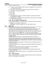
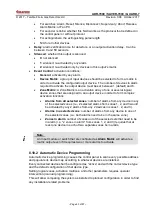
Screen 69 Automatic device programming 


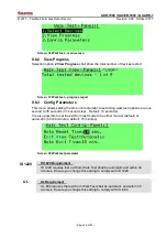
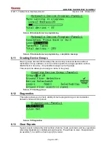
Screen 70 Automatic device programming 

– completion message 

8.11 

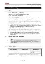
Creating Device Groups 

Device groups are intended to assign the same entity to several devices without 
restrictions of loop, address, or zone in order to perform a single operation such as 
disablement in one step.  It is possible to assign up to 20 groups. 

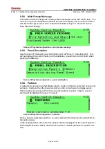
The second line allows you to assign a name to the group. 


Screen 71 Creating groups 

8.12 

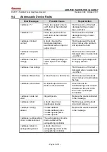
Diagnostics 

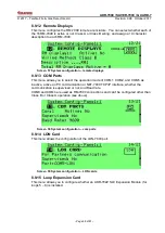
This option allows you to check validity of device programming or communication 
between various control panels. 


Screen 72 Diagnostics 

8.13 

Clear Reports 

System reports indicate the total number of alarms, faults, walk tests, and key operations 
(silencing, disablement, enablements and resets).  Press Enter to clear.  Respond with 
an asterisk (*) to confirm or hash sign (#) to cancel. 

Summary of Contents for ADR-7000

Page 1: ...essable Fire Alarm Control Panel Technical Manual TELEFIRE FIRE GAS DETECTORS LTD PO Box 7036 Petach Tikva 49250 Israel Tel 972 3 970 0400 Fax 972 3 921 1816 eMail info telefire com Web www telefire c...

Page 2: ...guideline and UL standards and Fault as used in EN 54 standards are used interchangeably throughout this manual i Note Do not install operate and maintain this ADR 7000 before fully reading this manua...

Page 3: ...E ANNUNCIATOR RM 7000 7 2 10 ACCESS LEVELS 8 3 WORK STATES ALARM FAULT SUPERVISORY DISABLEMENT AND TEST MODES 10 3 1 NORMAL QUIESCENCE STATE 10 3 2 ALARM STATE 10 3 3 FAULT STATE 12 3 4 SUPERVISORY ST...

Page 4: ...TEM CONFIGURATION PROGRAMMING 41 8 1 SYSTEM CONFIGURATION 41 8 2 ENABLEMENT DISABLEMENT 42 8 3 MONITOR 44 8 4 SYSTEM REPORTS 44 8 5 UTILITIES 48 8 6 WALK TEST 51 8 7 SYSTEM VIEW 53 8 8 SMOKE CONTROL T...

Page 5: ...SUPPLY 78 13 3 REMOTE ANUNCIATORS 78 13 4 MAIN BOARD FIELD CONNECTION 78 13 5 MAIN BOARD RELAYS 79 14 CERTIFICATION 80 APPENDIX A CURRENT CONSUMPTION AND BATTERY CAPACITY CALCULATION 81 WHEN ARE AUXIL...

Page 6: ...rm verification by cross zone Yes Cross zone or no verification Cross zone or no verification Do not combine time based alarm verification and cross zone alarm verification Delay of releasing Yes 0 50...

Page 7: ...rawn from them exceeds the specified amount Input and output protection is done without the use of fuses using an advanced current management that allows for high resilience of the system when encount...

Page 8: ...n keyboard or with Telefire proprietary PC based software The ADR 7000 s sophisticated microprocessor allows easy configuration and modification in the field without the use of dedicated tools while p...

Page 9: ...propriate programming each control panel on the network is able to respond to alarm and trouble events that occurred in other control panels The control panel has an integral real time clock and calen...

Page 10: ...nciator units 2 2 SLC Line Card ADR 7002 Up to four ADR 7002 line cards line cards are mounted on the ADR 7021 main board and control the bi directional communication between the control panel and the...

Page 11: ...ct standards of UL 864 EN 54 and IS 1220 The display and keypad have six main areas Graphic LCD display General display area Fault display area Additional indication area Keyboard Zone indication LEDs...

Page 12: ...k may be bus figure 8 ring figure 9 or free figure 10 topology Logical hierarchy may be peer to peer where all messages are reported in all control panels master slave where slave messages are reporte...

Page 13: ...000 remote panel consists of an LCD display keyboard internal buzzer and features such as alarm output trouble output and an interface relay that reduces the need for additional input output interface...

Page 14: ...ns such as configuration and programming Access level 4 manufacturer protected by dedicated tool There are six users each of which has a different password User Position User 1 Security guard User 2 O...

Page 15: ...r 2017 Page 9 of 87 Action User 1 Users 2 and 3 Users 4 and 5 User 6 Guard Operator Programmer Senior Programmer Device programming Keyboard unlock Clearing extinguishing activated sign Can change pas...

Page 16: ...first To see the events in the order they occur use the up and down arrow keys 3 1 Normal Quiescence State Normal state is a state where no alarm or fault event and all of the inputs and outputs are...

Page 17: ...panel Activating dialer output Activating internal buzzer Activating relays that were configured as alarm relays Activate output addresses as per matrix configuration 3 2 3 Acknowledge Buzzer Off Ope...

Page 18: ...a fault event at the control panel the control panel will perform the following operations Indicating the fault in the display Turning on the General Fault LED Activating the internal buzzer in the co...

Page 19: ...Logging of the event in the fault history Activating supervisory outputs that are in the same logical zone as the activated fault supervisory device if defined Activating supervisory relays if defined...

Page 20: ...page Error Bookmark not defined for additional information about Field Test 3 7 Status State Screen 8 Status state Status state indicates events that are not alarm supervisory fault disablement or tes...

Page 21: ...The NFPA National Fire Protection Association is the American association for the fire safety industry Its guideline NFPA 72 National Fire Alarm and Signaling Code specifies the application installat...

Page 22: ...addresses 3 3 ADR 741 Relay module 1 ADR 812A Two Channel Input Module configured as a single input 4 1 ADR 812A Two Channel Input Module configured as two inputs 4 2 ADR 805A Flow Switch Interface M...

Page 23: ...ot found page Error Bookmark not defined for additional details An external power supply TPS 74A or TPS 34A is required if any of the following conditions are met Quiescence normal mode current consum...

Page 24: ...th for given cross section 18 AWG 0 8 mm2 950 m 3 130 ft 16 AWG 1 3 mm2 1 520 m 4 970 ft 14 AWG 2 1 mm2 2 420 m 7 940 ft 12 AWG 3 3 mm2 3 830 m 12 580 ft Table 4 Maximum SLC Loop Length 4 2 3 Cable Pl...

Page 25: ...ble commonly referred to as STP Category 5 cable is defined by the EIA TIA ANSI 568 specification The extremely high volume of Category 5 cable used makes it widely available and very inexpensive ofte...

Page 26: ...pplies are required if one or more of the following conditions is true The quiescence 24V current draw exceeds the control panel s power supply limitations 0 5A for ADR 4004TSW The 24V current draw in...

Page 27: ...to the system 4 4 1 Mounting the Control Panel s Cabinet The control panel s cabinet should be installed in a clean dry vibration free indoor location Avoid exposure to severe conditions such as high...

Page 28: ...ADR 7000 SAVER 7000 GUARD 7 2017 Telefire Fire Gas Detectors Ltd Revision 0 98 October 2017 Page 22 of 87 Figure 4 Mounting holes in the Chassis...

Page 29: ...23 of 87 Figure 5 Mounting Figure 6 Flush Mounting The wiring opening on the top right of the cabinet should be covered with a metal sheet If no wires enter the cabinet through this opening close it...

Page 30: ...ited circuit wiring must be at least 0 25 6 35mm away from any non power limited circuit wiring Use different entries of the cabinet or conduits See Figure 27 on page 11 4 4 2 Field Connection Diagram...

Page 31: ...ions of the loop to the control panel Make sure that the resistance does not exceed 40 Repeat for each input or SLC For systems that have an NFPA SLC style 4 T branching repeat the test for each branc...

Page 32: ...wiring to ensure there are no shorts or ground faults prior to connecting field cabling to the control panel Connection or adding loops i o modules detectors etc will be performed when all power supp...

Page 33: ...ion Error Reference source not found on page Error Bookmark not defined The control panel shall scan every address on every loop Every device that is physically connected to the control panel shall au...

Page 34: ...ation in the labyrinth chamber due to accumulation of oil residue and dust This accumulation may shorten the detectors life span and require it to be sent to the factory for cleaning 4 5 3 Verificatio...

Page 35: ...alid password Once you have changed the password it is important that you write it down somewhere and store it in a safe place 4 5 6 System Documentation Attach the followings to the system s front pa...

Page 36: ...of the two operations IS 1220 IS 1220 Requirement Do not combine alarm verification utilizing delay and cross zone verification Total delay for activation of extinguishing detector verification delay...

Page 37: ...physical switch and not accomplished by software Extinguishing disconnect shall be shown as a supervisory event An extinguishing disconnect switch shall be installed near the extinguishing device Acti...

Page 38: ...med by authorized personnel Ensure that the control panel is back to normal operation UL 864 UL Requirement UL 864 paragraph 36 1 7 states that An automatic delay provided prior to release operation b...

Page 39: ...l Below these keys in a space for optional zone display LEDs The central part had a 260 by 64 pixel graphical LCD and various keys for the operator and allows the system Programmer Supervisor to execu...

Page 40: ...Pressing Acknowledge will turn the LED solid on until resolution of the problem PS Fault Yellow LED Indicates a power fault loss of AC power Disconnected battery Weak battery Off during normal operat...

Page 41: ...ion Off during normal operation Off during normal operation On following an abort A Reserved for future use Fire Red LED Indicates fire alarm The device in alarm is displayed on the LCD display Off in...

Page 42: ...Acknowledge will turn the LED solid on until resolution of the problem Solid yellow when horn output is disabled Silenced Red LED Yellow LED Indicates silenced condition Off during normal operation an...

Page 43: ...ll addressable outputs that are defined as silenced Reset Pressing this key resets and restores the system to normal operation mode All NACs are turned off input and output modules return to normal op...

Page 44: ...can be programmed and modified on site to respond to each site s specific requirements ADR 3000 programming requires level 3 access After entering programming mode it is possible to set system config...

Page 45: ...Entering Configuration State Press Menu and select 1 System Program Enter the password and press Enter 7 3 Configuration Process Programming the system is in five steps Enter programming state Progra...

Page 46: ...1 7 states that An automatic delay provided prior to release operation by a system shall be a maximum of 60 seconds timed from a release initiation condition either from the actuation of a single dete...

Page 47: ...220 EN 54 EN 12094 and GOST and may comply with options or requirements of one of the standards and are not compliant with another standard Where the control panel allows setting of a parameter that a...

Page 48: ...anel number and whether the operation shall be performed for a device a Zone a Group or Main Board Outputs Screen 12 Enable Disable primary screen Press Enter and you can see the following screen Scre...

Page 49: ...ice type you can select the specific device address 8 2 2 Enabling and Disabling a Zone Selecting Operation by Zone shall display the following screen Screen 14 Enable Disable Zone This operation allo...

Page 50: ...feature allows the graphic display of the physical sensor s output of a selected device You can also perform a test of the device Screen 17 Monitor Screen Sort by Address Screen 18 Monitor Screen Sort...

Page 51: ...er test key operations device list active outputs and preventive maintenance recommendations Screen 20 System reports alarms panel selection After selecting the panel it is possible to page though ind...

Page 52: ...en 27 System reports individual key operation Key Operation report displays activity reports for the following operations panel configuration hardware initialization advanced configuration device prog...

Page 53: ...ive at the moment You can select all loops a specific loop and either all devices or a specific device type sounder Lamp Extinguisher Extinguisher Control Control Out Supervisory Out or Fire Phone Lam...

Page 54: ...5 3 Revisions This option shall display hardware and software revisions of the following modules 1 CPU Card ADR 7007 2 SLC cards ADR 7002 3 Main Board ADR 7021 4 Display Card ADR 7003 5 LON Card LON 7...

Page 55: ...ation NFPA recommendation and local regulations in most countries require that the keyboard be locked Screen 32 Keyboard Locking mode selection 8 5 5 Time Date Program Use this menu to set the date an...

Page 56: ...hat occurs during night mode will activate the dialer immediately During day mode operation will be delayed if programmed thus Screen 34 Setting daily night and day times 8 5 7 Holidays Setting Here y...

Page 57: ...password From the main menu select 6 Walk Test The following message is displayed Key in 1 to select devices for testing The next menu shall allow the selection of loops zones or groups for testing P...

Page 58: ...walk test options are one second to 30 seconds in 1 second steps Default 10 seconds It is also possible to set the exit from test mode to be either manual default or automatic 5 to 60 minutes default...

Page 59: ...panel licensing See section 4 5 1 on page 28 for explanation about panel registration 8 7 2 View Devices Screen 40 System view view devices Pressing the Function key will allow to clear the selected d...

Page 60: ...it matches the specific site requirements 8 9 1 Panel Number This menu allows you to change the panel number when working in a networked system Select a number from 1 to 32 Screen 46 System configura...

Page 61: ...ayed for system faults such as batteries ground fault and AC fault when pressing the Info key Screen 48 System configuration panel description 8 9 4 Partners A networked control panel shall display al...

Page 62: ...nd NAC 2 and ADR 723 outputs that are configured to work in protocol operation jumper setting on the ADR 723 shall work in this protocol This protocol synchronizes strobes throughout the system and al...

Page 63: ...that is defined as Partner or only from this panel and the activation delay during day time hours 0 9 minutes in 1 minute increments Screen 55 System configuration alarm dialer 1 8 9 11 Dialer 2 Tr Th...

Page 64: ...u allows you to select the operation mode of COM1 COM2 and COM5 as inactive active an PC communication or NET 7000 TCP IP interface whether the communication is supervised or not and Baud rate COM3 an...

Page 65: ...er alarm initiation Leave this option at the default unless required by local standard regulation or authority having jurisdiction CP 10 CP 10 Requirement CP 10 requires that under certain conditions...

Page 66: ...n case of loss of AC mains supply The fault is indicated visually immediately regardless of this delay Range 0 240 minutes Default 0 minutes Screen 64 System configuration AC fault buzzer delay UL UL...

Page 67: ...al or automatic operation Manual shall allow you to set parameters for a specific address Manual shall scan through each possible address at each SLC Line Card Each existing device shall be configured...

Page 68: ...ut that activates a strobe Extinguisher an ADR 723 output that is used to release extinguishant The Mode field specifies pulse length 5 seconds to 239 minutes or continuous until reset Default is 15 s...

Page 69: ...rm complex activation functions Alarms from all selected zones number of alarms from any device in any of the selected zones i e 2 selected alarms from zones 1 2 and 3 would be activated by any 2 alar...

Page 70: ...rform a single operation such as disablement in one step It is possible to assign up to 20 groups The second line allows you to assign a name to the group Screen 71 Creating groups 8 12 Diagnostics Th...

Page 71: ...ogram Change password Default passwords are Operator 1 111111 Operator 2 222222 Operator 3 333333 Operator 4 444444 Operator 5 555555 Operator 6 666666 8 15 Advanced Not for field use 8 16 Detector In...

Page 72: ...66 of 87 Pressing Enter will activate the fast Initializing The system will display the message DONE upon completion Pressing the Quit key exits this window without performing the fast update i Note E...

Page 73: ...light LED 4 indicates a communication fault including in the event of a momentary fault that does not activate a system wide fault mode 9 1 3 LEDs on the Loop Card The LEDs at the line cards have elec...

Page 74: ...he fault damaged wire or a water leak and fix it Main circuit device low voltage The voltage is low on the designated device AC1N 24V A output circuit dial up alarm dialer FWRE dial up connection fail...

Page 75: ...oltage fault Check the input voltage and its supply sources address low voltage Find the source of the fault damaged wire or a water leak and fix it address Blown fuse A blown fuse in a 24V device Fin...

Page 76: ...the extinguishing controller Reconnect address short circuit on the pressure switch Short circuit on pressure switch at the extinguishing controller Reconnect address abort extinguishing is disconnect...

Page 77: ...the number of input devices required activate the output or add input devices to the operation matrix Input device listed in matrix has been cancelled This message will be received when the one of the...

Page 78: ...e number of devices in the selected areas An alert that the selected number of alerts required to activate an output device is greater than the total number of input devices in the selected under the...

Page 79: ...a phone call on a fireman phone system or Extinguishing Abort or Extinguishing Hold in progrees Information only no need for any action 9 7 Control Panel Network Faults Error Messages Possible Cause R...

Page 80: ...visor should inspect the control panel weekly and verify that all of the following conditions exist The green LED is on and is not blinking None of the yellow or red LEDs are on or blinking The contro...

Page 81: ...the manufacturers instructions and the applicable standards are a conditioned precedent for the proper and efficient function of the system The designer and installer should have the appropriate skil...

Page 82: ...282F TFH 282R TFH 283F TFH 283R and TFH 220F conventional heat detectors TPB 10R TPB 10Y and TPB 10B conventional call points TXB 435 barrier 12 1 3 Connection via a TRA 1 Adaptor and an Input Module...

Page 83: ...s cylinders via TLA 23 adaptor Firepro aerosol generators via TLA 44 adaptor Greenex aerosol generators via TLA 33 adaptor 12 2 4 Other devices LI 3000 LI 3000C and LI 3000E short circuit isolators TP...

Page 84: ...faults Drift compensation update time 3 hours 13 2 Power Supply The ADR 7000 contains a 150W power supply The SAVER 7000 and GUARD 7 contain a 100W power supply Battery charging automatic variable cur...

Page 85: ...e SLC card 1 24 V_A Dialer mode constant voltage supply current protection electronic max current 0 3A 24Vdc Dialer activation mode level activation max current AL output 70mA 24Vdc max current TR out...

Page 86: ...as Detectors Ltd Revision 0 98 October 2017 Page 80 of 87 14 Certification Telefire s ADR 7000 Addressable Control Panels have the following approvals EN 54 Approved UL 864 Edition 10 Listed GOST Appr...

Page 87: ...mA TIP 224 X 0 mA 0 40 0 mA Other NAC X mA mA Other NAC X mA mA Other NAC X mA mA Current to loops TFO 480A 440A X 0 29 mA 2 6 mA TFH 280A 220A X 0 20 mA 2 6 mA TPH 482A 442A X 0 29 mA 2 6 mA TFL 1AN...

Page 88: ...A 70 0 mA TLA 22 X 2 0 mA 0 0 mA TLA 23 X 2 0 mA 0 0 mA TLA 33 X 3 0 mA 0 0 mA TLA 42 X 2 0 mA 0 0 mA TLA 44 1 or TLA 44 X 5 0 mA 0 0 mA TLA 110 X 1 5 mA 0 0 mA TLA 120 X 1 5 mA 0 0 mA TLA 130 X 1 5 m...

Page 89: ...battery enclosure can contain two 12V sealed lead acid batteries up to 20 W by 7 D by 12 H cm each For fire alarm control panels requiring larger batteries use the BC 3000 external battery enclosure...

Page 90: ...A in alarm The total power consumption of the control panel the control panel itself and devices attached and powered by it is more than 4 0A in alarm There is a requirement for batteries with more th...

Page 91: ...ge of 7 C minute 13 C minute in 1 C minute steps Sensitivity Least Sensitive Default Most Sensitive Fixed Temperature 90 C 50 C 50 C Rate of Rise 13 C per minute 9 C per minute 7 C per minute Table 2...

Page 92: ...put to alarm devices Section 7 9 Control of fire alarm routing equipment Section 7 10 Outputs to fire protection equipment Section 7 11 Delays to outputs Section 7 12 Dependencies on more than one ala...

Page 93: ...extinguishing signal Section 4 18 Signal representing the flow of extinguishing agent Section 4 19 Monitoring of the status of components Section 4 20 Emergency hold device Section 4 21 Control of flo...

Reviews: