ADR-7000 / SAVER-7000 / GUARD-7
© 2017
– Telefire Fire & Gas Detectors Ltd
Revision 0.98 October 2017
– Page 18 of 87 –
Class A configuration requires a minimum of one LI-3000 or LI-3000E module per loop.
The outgoing wiring in Class B or Class A cabling should be connected to the SLC Out
terminator on the left (marked as
), and the Class A return wire to the terminator on the
right (marked as
).
A group of devices should be connected in a section between two isolators. Each
section is protected from short-circuit that may occur in other loop sections. Configure
the loop card as Class A.
Configuring a loop as Class A does not reduce loop capacity, other than the addresses
taken by the isolation modules. Each SLC loop is capable of addressing 127 devices,
including the addresses occupied by the LI-3000 modules.
Use up to 20 LI-3000 line isolators per SLC loop.
i
Note
Class A is defined per line card in the ADR-7000. In a control panel that has
more than one line card, it is possible to have some of the line cards working
in Class A, and the others working in Class B.
4.2.2 Cable Planning
– SLC (Loop) Cable Selection
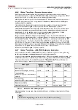
Use a twisted pair wire 18 to 12 AWG and follow the guidelines in the table below for
wire selection.
Wire Type
Cross-Section
Maximum SLC Branch Length for given cross-
section
18 AWG
0.8 mm
2
950 m
3,130 ft.
16 AWG
1.3 mm
2
1,520 m
4,970 ft.
14 AWG
2.1 mm
2
2,420 m
7,940 ft.
12 AWG
3.3 mm2
3,830 m
12,580 ft.
Table 4
Maximum SLC Loop Length
4.2.3 Cable Planning
– 24Vdc Supply to Devices
The length of activation lines and 24Vdc Out cabling depends on the required current
and cable size. Cable resistance running between the 24Vdc source to the I/O module
and from the I/O module to the device should be calculated. Ensure that no device
receives a voltage below its specified minimum operating value and that the total voltage
drop will not exceed 2 volts, (i.e., the last device on the line receives at least 22Vdc
when activated).
4.2.4 Cable Planning
– 24Vdc Supply to ADR-823A Modules
It is recommended to use ADR-723 with the ADR-7000. If there is a need to use
ADR-823A modules with the ADR-7000, use an LDO-7000 voltage adaptor connected to
the 24Vdc output on the ADR-7000. Connect the ADR-7000's 24Vdc output to the
In
TB
of the LDO-7000, and the
Out
TB of the LDO-7000 to the field.
4.2.5 Cable Planning
– NAC Outputs
The length of NAC activation lines cabling depends on the required current and cable
size. Cable resistance running between the NAC outputs to the device should be
calculated. Ensure that no device receives a voltage below its specified minimum
operating value and that the total voltage drop will not exceed 2 volts, (i.e., the last
device on the line receives at least 22Vdc when activated).


