Operator’s Manual Simple AFG Application
73
Is Enabled
It enables or disables the Marker Out. When the Marker Out is disabled, it
is forced to 0 V.
Marker Skew [s]
(
Run
Mode Contin. or
Modul
)
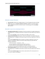
It sets the delay between the marker and the analog channel. This
parameter is valid only if the run
Continuous Mode
or
Modulated Mode
or
Sweep Repeated Mode
is been selected for the associated channel to
the Marker out.
The skew range is
0s
to
14s
.
Marker Skew [s]
(
Run
Mode Burst or
Sweep Trig.
)
It sets the delay between the marker and the analog channel. This
parameter is valid only if the run
Sweep Triggered Mode
or
Burst Mode
is
been selected for the associated channel to the Marker out.
The skew range is
0s
to
3us
.
Link To
Since there is one Marker Out signal for each couple of analog channels,
using this parameter it is possible to choose which analog channel is
related to the Marker Out N signal.
Please note that
•
Marker Out 1
can be linked to Channel
1
or Channel
2
•
Marker Out 2
can be linked to Channel
3
or Channel
4
•
Marker Out 3
can be linked to Channel
5
or Channel
6
•
Marker Out 4
can be linked to Channel
7
or Channel
8

