


Maintenance—Type
502A
1.
Use
a
soldering iron of about 75-watt
rating.
2. Prepare
the tip
of the iron as shown in Fig. 4-1.
3.
Tin
only
the first 1/16 to 1/8 inch of the tip. For
soldering
to
ceramic terminal strips tin the iron with solder
containing about
3% silver.
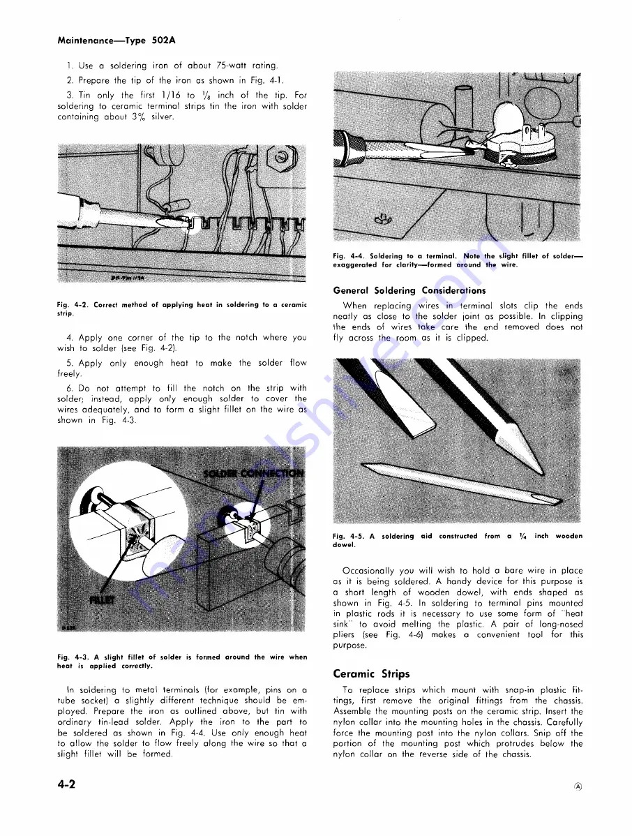
Fig.
4-2. Correct method of applying heat in soldering to a ceramic
strip.
4. Apply
one corner of the tip to the notch where you
wish
to solder
(see Fig. 4-2).
5.
Apply
only enough
heat to make the solder flow
freely.
6.
Do
not attempt to fill the notch on the strip with
solder;
instead,
apply only enough solder to cover the
wires
adequately, and to form
a
slight fillet on the wire as
shown
in
Fig. 4-3.
Fig.
4-3.
A
slight fillet of solder is formed around the wire when
heat
is applied correctly.
In soldering to
metal terminals (for example, pins on a
tube
socket) a slightly different technique should be em
ployed.
Prepare the iron as outlined
above, but tin with
ordinary
tin-lead solder. Apply the iron to
the part to
be soldered as shown in Fig. 4-4.
Use only enough
heat
to
allow
the solder to flow freely along the wire so that a
slight
fillet will
be formed.
Fig.
4-4. Soldering to a terminal. Note the slight fillet of solder-
exaggerated
for clarity—formed around the wire.
General
Soldering Considerations
When
replacing wires in terminal slots
clip the ends
neatly
as
close to the solder joint as possible. In clipping
the
ends of wires take care the end removed does not
fly
across the room
as it is clipped.
Fig.
4-5.
A soldering aid constructed from a 1/4 inch wooden
dowel.
Occasionally
you will wish to hold a bare wire in place
as
it
is being soldered. A handy device for this purpose is
a
short length of
wooden dowel, with
ends shaped as
shown
in Fig.
4-5. In soldering to terminal
pins
mounted
in
plastic
rods
it is necessary
to use some form of ' heat
sink''
to
avoid melting the plastic. A pair of long-nosed
pliers
(see
Fig. 4-6) makes
a convenient tool for this
purpose.
Ceramic
Strips
To
replace strips which mount with
snap-in plastic fit
tings,
first remove the original fittings from the chassis.
Assemble
the mounting posts
on the ceramic
strip. Insert the
nylon
collar into the mounting holes in
the chassis. Carefully
force
the mounting post
into the nylon collars. Snip off the
portion
of the
mounting post which protrudes
below the
nylon
collar
on
the reverse side of the chassis.
4-2
Summary of Contents for 502A
Page 4: ......
Page 22: ...Circuit Description Type 502A Fig 3 2 Simplified Sweep Trigger Circuit t i CO ...
Page 27: ...Circuit Description Type 502A Fig 3 4 Simplified Horizontal Amplifier 3 9 ...
Page 32: ...Circuit Description Type 5O2A Fig 3 7 Simplified Calibrator Circuit 3 14 ...
Page 34: ...NOTES ...
Page 56: ...NOTES ...
Page 60: ...Parts List Type 502A LEFT SIDE 6 4 ...
Page 64: ...Parts List Type 502A RIGHT SIDE 6 8 ...
Page 67: ...Parts List Type 502A TOP 6 11 ...
Page 70: ...Parts List Type 502A BOTTOM 6 14 ...
Page 73: ...Parts List Type 502A REAR 6 17 ...
Page 89: ...TYPE 502A OSCILLOSCOPE A ...
Page 90: ...A BLOCK DIAGRAM MRH Z6 3 ...
Page 91: ... TYPE 502A OSCILLOSCOPE A ...
Page 92: ...A CIRCUIT NUMBERS 1 THRU 59 I Ixj 263 TIME BASE TR IGGER ...
Page 93: ......
Page 95: ...TI M I NG RESI 5TORS TIMING CAPACITORS TYPE 502A OSCILLOSCOPE ...
Page 96: ...SWI6O HOLD OFF CAPACITORS 4 RESISTORS TIM ING CAPACITORS o A TIMING SWITCH job ...
Page 98: ... 1 INPUT AMPLIFIER OUTPUT AMPLIFIER A CIR CUIT NUMSER 5 300 THR U 399 ZG3 joe ...
Page 100: ...CMO 363 VERTICAL ATTENUATOR SWITCH A ...
Page 103: ...TYPE 5O2A OSCILLOSCOPE OOM HEATER WIRING DIAGRAM ...
Page 104: ...POWER SUPPLY CIRCUIT NUMBERSI 600 THRU 799 ...
Page 106: ...CIR CUIT NUMBER S 800 THR U 869 CRT CIRCUIT c 9G4 ...
Page 107: ...CA LIBp A TOp MULTIVIBP A TOR 1 IOOV o TYPE 5O2A OSCILLOSCOPE A ...
Page 108: ...CAL OUT CF CALIBRATOR A CIRCUIT NUMBERS 8 7O THRU 899 4Z ...


