1.
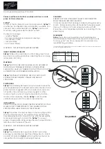
Set the controls as follows:
POWER
ON
INPUT COUPLING
GND
TRIGGER
AUTO
LEVEL-SLOPE
Midrange of either slope
(do not set at control
midrange)
VOLTS-mA/DIV VAR
CAL detent
HORIZ MGF VAR
CAL detent
POS (both)
Midrange of control
DMM (OUT:SCOPE)
Button out
RMS (OUT:DC)
Button out
VOLTS
Button in
VOLTS-mA/DIV
1 (blue scale)
SEC/DIV
.5 m
INTENSITY
Minimum for a visible
trace
2. Set the SEC/DIV control to .5 and adjust the FOCUS con
trol (screwdriver adjustment on the side panel) for the best
spot definition (the dot will be slowly sweeping across the
screen from left to right).
3. Set the SEC/DIV control to .5 m and adjust the vertical
POS control so the trace coincides with the center horizon
tal graticule line. If the trace is not parallel with this line,
adjust the TRACE ROTATE control (screwdriver adjustment
on the side panel) for coincidence.
4. Depress the DMM pushbutton. Alternately switch the
VOL TS-mA/DIV control between the 0.1 volt and 1 volt
ranges (blue scale) and check for the same count (approxi·
mately zero) and polarity sign in both positions. If they
are not the same, adjust DC BAL (screwdriver adjustment
on the side panel) for the same count and polarity sign.
DIGITAL MULTIMETER DISPLAYS
Voltage Measurement Display
1. Perform the Operators Adjustments steps.
2. Set the INPUT COUPLING switch to DC, select a VOL TS
mA/DIV range (blue scale) compatible with the amplitude of
the de voltage source to be measured, and connect the de vol
tage source between the probe tip and the probe common
clip. The display represents the value of the de voltage
source.
@
213 Operators
15
Summary of Contents for 200 Series
Page 1: ...213 DMM OSCILLOSCOPE WITH OPTIONS OPERATORS ...
Page 2: ... ...
Page 8: ...213 DMM Oscilloscope 213 Operators ...
Page 52: ......
Page 54: ......
Page 55: ... ...
Page 56: ......