


12
Test button
The control can be made to cycle through a test routine whenever the Test button is pushed. The
test can be halted at certain times by pushing the button a second time. For details of the test
routine, refer to the description starting on the next page.
Test
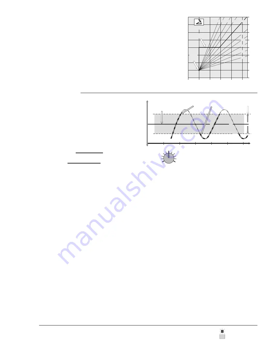
Boiler Differential and Time Delay
The Boiler Differential adjustment sets how much the actual
supply water temperature may deviate from the desired tempera-
ture before stages are turned on or off, and is determined by the
flow rate past the supply sensor relative to the amount of heat
produced by each stage. To prevent short operating cycles of the
boilers the control has a delay of at least 1 minute between firing
cycles. On an installation where flow rates are known, the Boiler
Differential can be calculated as follows:
Desired temperature
this example
160
°
F(71
°
C)
T
emperature
W
armer
Cooler
Time
Differential
this example
10
°
F(5
°
C)
165
°
F(74
°
C)
155
°
F(68
°
C)
Te
m
p
e
ra
tu
re
fa
ll
Staging
OFF ON
Te
m
p
e
ra
tu
re
r
is
e
Boiler Differential =
For example:
=
10
°
F (6
°
C)
Btu/hr
US GPM x 500
100,000 Btu/hr
20 US GPM x 500
Trial setting = 22
°
F if
flow rates are unknown
22
°
F
2
42
Boiler
Differential
All boilers will eventually turn on when the temperature falls
and stays 5
°
F (3
°
C) below the desired temperature. Delays of 1 to
5 minutes for staging on depend on the degree of control error (P+I+D). As the temperature rises to within the differential range,
no boilers are staged on or off. All boilers will eventually turn off when the temperature rises
and stays 5
°
F (3
°
C) above the desired
temperature. Delays of 8 seconds to 3 minutes for staging off depend on the degree of control error.
Setting a boiler differential for modular boilers is often complicated
by the fact that flow rates and heating loads may vary widely, and
at times boiler outputs may not be balanced to the load. Observing
the "Target Supply" fixed display while the boilers are staging can
assist the user in understanding system flow and boiler problems.
The ideal control reaction occurs when the target supply tempera-
ture remains constant or only changes slightly during the staging
process, indicating a well balanced and constant – or slowly
changing – load vs. output in the system.
If the target supply temperature decreases
rapidly when a boiler
comes on, it indicates a heavy derivative action by the control in
response to a rapid supply temperature increase. This type of
action typically indicates a condition where the boiler output is far
in excess of the load, a situation that is usually the result of a system
that is operating with only a few zones open (decreased load).
Setting a wider differential and ensuring a minimum fixed load (wild
loops) can help minimize this problem.
If the target supply temperature increases
rapidly, it indicates a
heavy derivative action by the control in response to a rapid load
increase. This type of action typically indicates situations where the
load is not finely divided (a few large zones) and is usually the result
of one large zone opening – or a system coming out of setback –
and delivering cold water to the boilers (increased load). Typically,
this will cause many or all of the boilers to be staged on with
minimum delay, which is the correct control action for the situation.
If the load fluctuates rapidly and repeatedly from heavy to light,
some instability may result in the staging process as the control
tries to bring on many boilers at once and then shut them off again
when the load suddenly decreases. The target temperature will be
constantly increasing and decreasing. Setting a wider differential
will help to stabilize the control action in many of these cases.
If the target supply temperature slowly and continually climbs, it
indicates that the supply temperature is not rising to the target
temperature. The control will continue to request more and more
boilers until the supply temperature rises sufficiently to reduce the
control error. This problem is called "Reset Windup" and can occur
in systems where: (a) the boilers are undersized, (b) flow is
interrupted –
without removing the heat demand – to the point
where the supply sensor cannot detect the supply temperature
increase, or (c) where the supply sensor is incorrectly placed – ie.
on the wrong pipe or on the
return of a system with very long runs.
The problem must be identified and corrective action taken.
If the target supply temperature slowly and continually decreases
after the boilers have been shut down, it indicates that the supply
temperature is hotter than the target temperature. This can happen
in systems with high mass boilers where the flow has been stopped
without using the heat demand input to the control, and convection
from the still hot boiler continues to heat the supply sensor. If the
heat demand input is used to shut the system down, the control will
ignore the sensor reading during the off cycle.
Overheating of buildings in warm weather will occur where minimum boiler temperatures are
required, unless the building has either a mixing system to reduce system supply water
temperatures to below boiler minimums, or some sort of room temperature control and zoning
system. Zone controls from tekmar, when used in these applications, will provide room
temperature feedback information to this control, allowing it to shift the heating curve for
maximum comfort and energy savings.
Typical Minimum Boiler Operating Temperatures: • Steel Tube Boilers …140
°
to 180
°
F (60
°
to 82
°
C) • Cast Iron Boilers …130
°
to 150
°
F (54
°
to 66
°
C) • Copper Tube Boilers …105
°
to
150
°
F (41
°
to 66
°
C) • Condensing or Electric Boilers …Off
Note: If the control is being operated in the setpoint mode and a boiler minimum setting is
selected, the user will be unable to program a setpoint lower than the minimum temperature
plus 1/2 of the Boiler Differential setting. If the minimum dial is set higher than the setpoint
less 1/2 the Boiler Differential, the setpoint will automatically be raised as the dial is turned
up. If the dial is then turned back down, the setpoint will have to be re-programmed.
Outdoor air temperature
Supply water temperature
50
(10)
30
(-1)
10
(-12)
-10
°
F
(-23)
°
C
110
(43)
70
(21)
70
(21)
90
(32)
210
(99)
170
(77)
150
(65)
130
(54)
190
(88)
3.6 3.0 2.4 2.0
0.8
0.4
1.0
0.6
90
(32)
50
°
F
(10)
°
C
Heating
Curve
1.2
Minimum Supply
Setting 130
°
F
WWSD
Point
70
°
F
1.6


