


58
Parameter
Signal
Name & Function
Default
Unit
Setting
Range
Control
Mode
Chapter
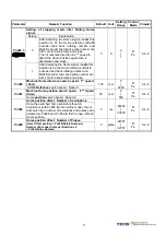
DI-2 Programmable Digital input Selection
★
Hn502
Please refer to
Hn501
002 X
001
│
11C
ALL 5-6-1
DI-3 Programmable Digital input Selection
★
Hn503
Please refer to
Hn501
003 X
001
│
11C
ALL 5-6-1
DI-4 Programmable Digital input Selection
★
Hn504
Please refer to
Hn501
104 X
001
│
11C
ALL 5-6-1
DI-5 Programmable Digital input Selection
★
Hn505
Please refer to
Hn501
105 X
001
│
11C
ALL 5-6-1
DI-6 Programmable Digital input Selection
★
Hn506
Please refer to
Hn501
006 X
001
│
11C
ALL 5-6-1
DO-1 Programmable Digital Output Selection
Setting Explanation
007 X
001
│
11C
ALL 5-6-1
Signal Functions
01
RDY
Servo Ready
02
ALM
Alarm
03
ZS
Zero Speed
04
BI
Brake Signal
05
INS
In Speed
06
INP
In Position
07
HOME
HOME
★
Hn507.0
★
Hn507.1
08
INT
In Torque
01 X
01
│
08
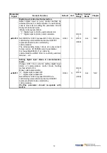
DO-1 Digital Output
Logic State.
Setting Explanation
0
Close, when the output is activated.
★
Hn507.2
1
Open, when the output is activated.
0 X
0
│
1
ALL 5-6-1
DO-2 Programmable Digital Output Selection
★
Hn508
Please refer to
Hn507
002 X
001
│
108
ALL 5-6-1
DO-3 Programmable Digital Output Selection
★
Hn509
Please refer to
Hn507
003 X
001
│
108
ALL 5-6-1
★
New setting will become effective after re-cycling the power.
Warning!
If any of programmable Inputs of DO-1 ~ DO-3 are set for the same type of function
then the logic state selection ( NO or NC selection) for these inputs must be the same type.
Otherwise an Alarm will be displayed. AL-07 (Abnormal DI/DO programming).
Summary of Contents for JSDE Series
Page 26: ...26 2 3 3 Position Control Mode Pi Mode Digital input and output terminal are programmable ...
Page 27: ...27 2 3 4 Speed Control Mode S Mode Digital input and output terminal are programmable ...
Page 28: ...28 2 3 5 Torque Control Mode T Mode Digital input and output terminal are programmable ...


