background image

2800 LAURA LANE • MIDDLETON, WI 53562 • (800) 288-9383 • FAX (608) 836-9044 • www.tcsbasys.com

4

fan

Occupied

Heating

Cooling

Fan

Service

Program/

COOLER

WARMER

Data

switch

system

switch

program

setup

clock

setup

override

service

status

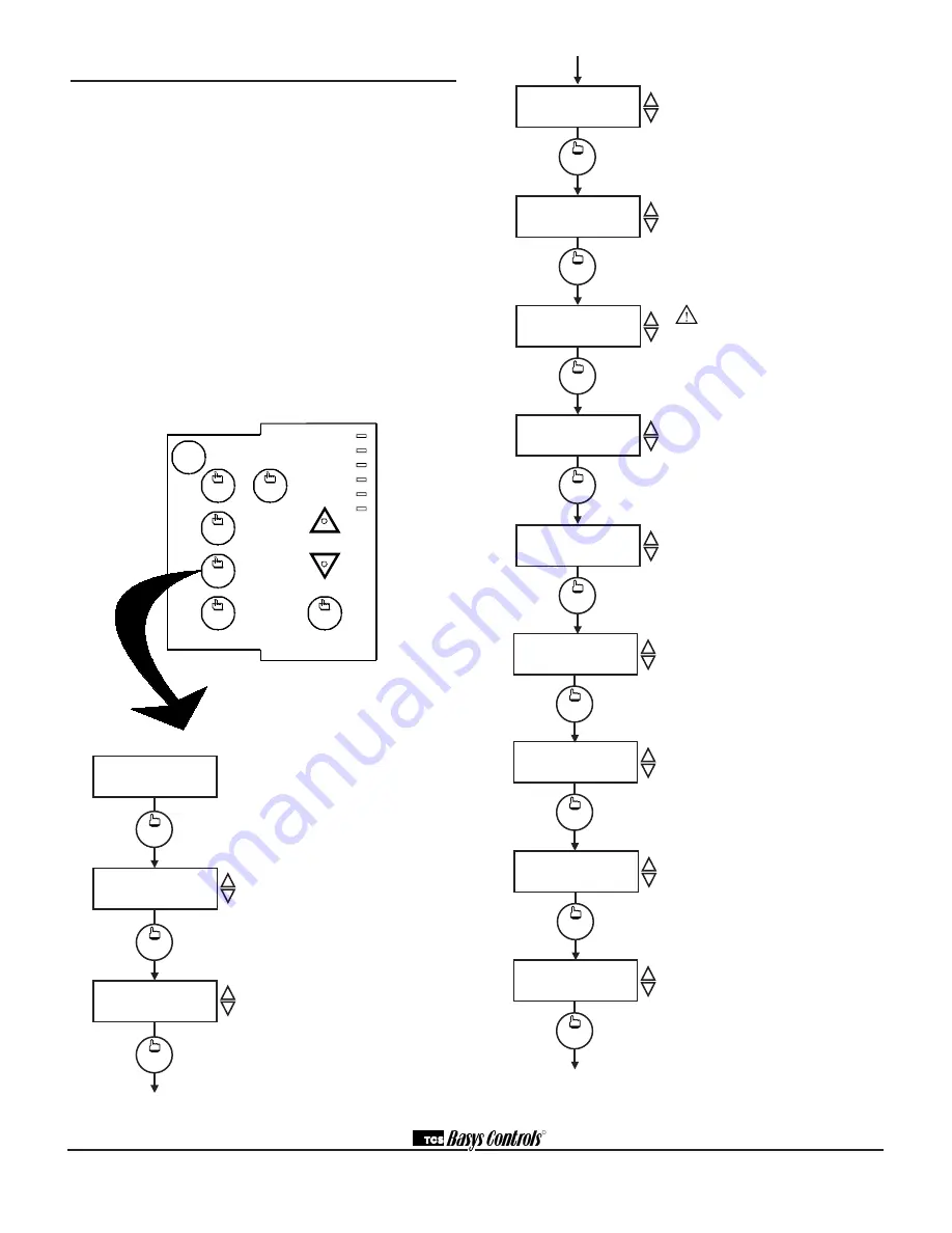
Main Monitoring Screen.

 Press the pro-

gram setup button to access the following 

screens. (Date not shown on SZ1024.)


Access Code Entry Screen.

 Will appear if 

access code is required for programming. 

Use 248 as the default. If the wrong code is 

entered, it will revert to the previous screen. 

Controller Address Screen.

 If using a 

PC to access the SZ1024 or SZ1033 set 

a unique address from 0 to 255, excluding 

248.

Programming                          

The SZ1024 and SZ1033 may be programmed through 

the keypad on the face, or with a PC. 
If programming with a PC, the following must be set 

through the face prior to programming:
•  Address (step #2)

•  Baud rate (step #3)

•  Temperature scale (step #4) 
For more information on programming through the PC, 

consult your TCS software manual. 

PROGRAMMING THROUGH THE KEYPAD

To access the programming screens, press the program 

setup button. To make changes, use the warmer and 

cooler keys. Access may be locked out with dipswitches, 

or an access code may be required. 

R

SET ADDRESS:

000

program

setup

program

setup

2.

ENTER ACCESS 

CODE 

000

program

setup

1.

MON 

11-19-01

12:00 AM            72F

program

setup

SET BAUD RATE:

9.6k

3.

program

setup

TEMP SHOWN IN:

FAHRENHEIT

4.

program

setup

SET UNOCCUPIED

FAN MODE:       AUTO

11.

program

setup

SET OCCUPIED FAN

MODE: 

ON

10.

program

setup

USER  ACCESS TO

FAN MODE?           YES

9.

program

setup

SET SYSTEM

MODE: 

AUTO

7.

program

setup

USER ACCESS TO

SYSTEM MODE?  YES

6.

program

setup

CONTROLLER TYPE:

HEAT PUMP

5.

program

setup

OUTDOOR AIR HEAT

SETPOINT:           10F

8.

Communication Baud Rate Screen. 

If using a PC to access the SZ1024 or 

SZ1033, all controllers on a network 

must be set to the same baud rate. 

Choose between 2.4K, 4.8K, 9.6K and 

19.2K. 


Display Type Screen.

 Choose between 

FAHRENHEIT and CELSIUS for tem-

perature indication.


Choose between Heat Pump and 

Conventional operation. Unit will 

reset immediately after choice is 

altered. 

          WARNING

 if you switch between     

         Heat Pump and Conventional 

modes, digital output functions change. 

Refer to the mode conversion Table on 

Page 7.  All the rest of the menus will 

remain unaltered. Note, the unit will also 

reset (the screen will momentarily go 

blank).

System Access Screen.

 Choose 

whether or not to enable user’s access 

to the system switch to set the system 

mode. 


System Mode Screen.

 Choose from 

AUTO, HEAT, COOL, EMERGENCY 

HEAT or OFF for your system mode. In 

the OFF mode, no contacts shall close.

Outdoor Air Heat Setpoint Screen. 


Set the Outdoor Air Heat setpoint.


Fan Access Screen. 

Choose whether 

or not to enable the user’s access to the 

fan switch to set the occupied fan mode. 


Occupied Fan Mode Screen.

 Choose 

between ON (continuous) or AUTO for 

your fan run times during the occupied 

modes.

Unoccupied Fan Mode Screen.


Choose between ON (continuous) or 

AUTO for your fan run times in the 

unoccupied mode.

Summary of Contents for SZ1024

Page 1: ...ch is accessible for adjusting its settings Caution Remove power from thermostat prior to mounting Product Manual Description The SZ1024 and SZ1033 are microprocessor based programmable thermostats de...

Page 2: ...r must be used to power the Superstat Several S Series ther mostats may be powered from the same transformer provided that the transformer has sufficient power Superstats require 8W 24 VAC Caution Do...

Page 3: ...ir sensor only Using remote room sensor with both discharge and outdoor air sensors SZ1033 only KEYPAD ACCESS The dipswitches in the thermostat cover shown above must be set in order to lock the user...

Page 4: ...m setup SET UNOCCUPIED FAN MODE AUTO 11 program setup SET OCCUPIED FAN MODE ON 10 program setup USER ACCESS TO FAN MODE YES 9 program setup SET SYSTEM MODE AUTO 7 program setup USER ACCESS TO SYSTEM M...

Page 5: ...int for this occupied period Occupied Cool Setpoint Screen Set the cool setpoint for this occupied period Occupied Cool Setpoint Screen Set the cool setpoint for this occupied period Occupied Cool Set...

Page 6: ...y P or add a time factor P I Time Clock Output Screen Choose whether the auxiliary output will be OPEN during occupied periods and closed during unoccupied periods or CLOSED during occupied periods an...

Page 7: ...4 33 SZ1022 31 Compressor 1 Becomes Cool 1 Compressor 2 Becomes Cool 2 Aux Heat 1 Becomes Heat 1 Aux Heat 2 Becomes Heat 2 Emergency Heat Mode does not exist Aux Heat 1 Must be enabled Step 24 for hea...

Page 8: ...bled using the software the override also activates in occu pied mode and takes the thermostat into unoccupied mode In either case you are able to view the time remaining in the override period both w...

Page 9: ...ges will be turned off and will remain off until the discharge air temperature falls 3 below that limit If the LOW LIMIT is reached the fan and cooling stages will be turned off and will remain off un...

Page 10: ...IARY OUTPUT An auxiliary relay output is available to output a signal based on the occupancy status It is commonly used with an economizer minimum position control or to signal an outdoor air damper t...

Page 11: ...e reading Press the WARMER up button The setpoint adjustment screen should now be showing Press the WARMER button until the heating setpoint is greater than the current temperature by at least five de...

Page 12: ...the wiring Short terminals R to W1 W2 Y1 Y2 or B O and see if the heating or cooling comes on This is a check for a mechanical relay failure Both Heating and Cooling Are On If this occurs there are t...

Page 13: ...fan O ccupied Heating Cooling Fan Serv ice Program CO OLER W ARM ER Data switch service status system switch program setup clock setup override 11 19 01 Main Monitoring Screen Press the service butto...

Page 14: ...s described in the setup section User s Guide Inside the hinged door of the thermostat is the SuperstatTM User s Guide This guide is designed to assist the installer in explaining to the user how to o...

Reviews: