


2800 LAURA LANE • MIDDLETON, WI 53562 • (800) 288-9383 • FAX (608) 836-9044 • www.tcsbasys.com
12
7. Press the cooler (down) button until the heating set-
point is one degree less than the current tempera-
ture. The reversing valve, compressors, and heating
stage(s) will sequence off. The fan will turn off 2 min-
utes after the reversing valve.
8. Press the cooler button until the cooling setpoint is
less than the current temperature by at least five
degrees. The fan will come on. The compressors(s)
will sequence on after 30 seconds.
9. Press the warmer button until the cooling setpoint is
greater than the current temperature by one degree.
The compressor(s) will sequence off. The fan will turn
off 2 minutes after the last compressor.
10. Go back to programming step #15 and set the set-
point adjust limit back to the desired value. Make any
other changes in programming, clock, and schedule.
Set the fan and system modes to their desired set-
tings.
11. If using remote sensor(s), verify that the reading is
correct. If not, see
Wrong Temperature Display
in
Troubleshooting
section.
TROUBLESHOOTING
No Display
Check for 24 VAC on terminals “+24” and “-24”. Check
the cable connecting the cover to the base for a good
connection.
Fan Does Not Come On
The fan is on whenever the fan LED is on. If the fan
should be on, but the fan LED is off, check the fan and
system switch modes, and the unoccupied fan mode
in programming. If the fan is off but the fan LED is on,
check wiring. Short terminals “R” to “G” and see if the
fan comes on. This is a check for a mechanical relay
failure.
Heating or Cooling Does Not Come On
At least one stage of heating is on whenever the heat-
ing LED is on, and at least one stage of cooling is on
whenever the cooling LED is on. If heating or cooling
should be on but the heating or cooling LED is off,
check the fan and system switch modes. Also, check
the heating and cooling setpoints, offsets and differen-
tials, and the room temperature to be sure heating or
cooling should be on. If using outdoor air heating and
cooling lockouts, or discharge air high and low limits,
check their values to be sure heating or cooling is
allowed. If heating or cooling is off, but the correspond-
ing LED is on, check the wiring. Short terminals “R” to
“W1”, “W2”, “Y1”, “Y2”, or “B/O” and see if the heating
or cooling comes on. This is a check for a mechanical
relay failure.
Both Heating and Cooling Are On
If this occurs, there are two possibilities. Either the
reversing valve operation is set incorrectly, or the heat
pump requires a conventional thermostat for proper
operation. (See programming through the Key Pad,
Step 5).
Wrong Temperature Display
Initially, verify the wiring connections to check for
problems (poor connections, opens, or shorts). If the
temperature is at a minimum or maximum reading,
check that the sensor dipswitch positions are correct as
shown in the Setup section of this document. Also, ver-
ify the resistance reading for the sensor in question. A
remote sensor should read 1080 to 1090 ohms at room
temperature. The built-in sensor should read 108 to 109
ohms at room temperature. If any of the temperatures
are still reading slightly high or low, you can add in a
temperature offset (calibration) using Ubiquity or TCS
Insight. In Ubiquity, you can edit the calibration offset
for each temperature input (room, discharge, outdoor
air, etc.) on the controller's programming page. For
example, if the room temperature is reading 2 degrees
high, you would subtract 2 from the existing offset in
the room temperature calibration offset field and submit
the page. In TCS Insight, the process is similar. Refer
to the Calibrate Using TCS Insight Tech Bulletin # 1019
for details. As a last resort and only when directed to do
so by TCS technical support, you may be able to use
the on-board adjustment pots. Refer to the Thermostat
Sensor Calibration Tech Bulletin # 1005 for details.
Service LED is On
If the service LED is on, it may be for monitoring pur-
poses or it may indicate a critical problem. The first
monitoring screen accessed by pressing the service sta-
tus button will display why the light is on.
Outputs Will Not Shut Off
First check the room temperature and the setpoints and
determine whether the output should be on. There are
delays and minimum on and off times for the fan and
heating and cooling stages. Also, check the service
status menus to verify that the outputs are on. Turning
the system to “off” will instantly turn all outputs off. The
thermostat can be reset by pressing the system switch
button and the service status button simultaneously.
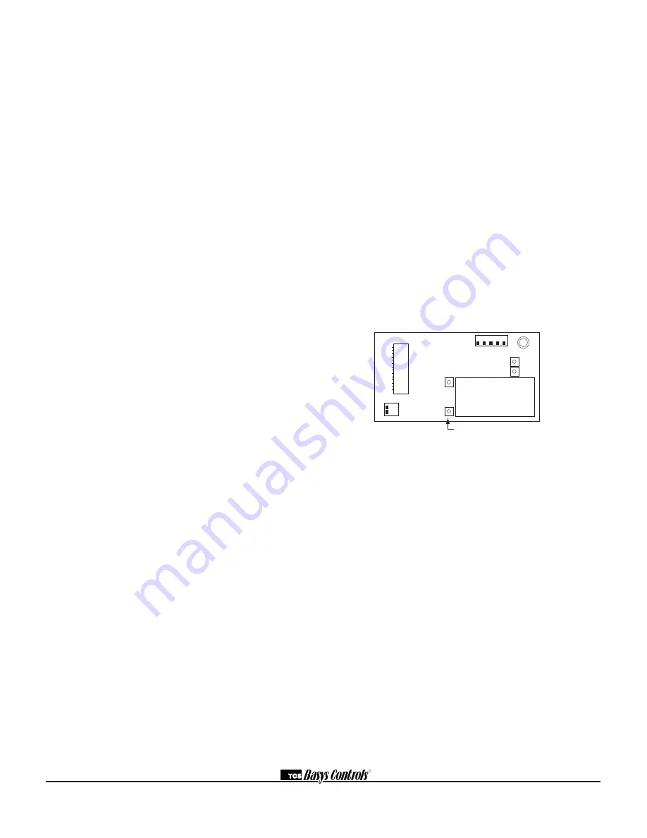
R
T1
T2
T3
1 2
1 2 3 4 5
adjust display contrast


