20
Primary part
General, Preparation
The following regulations must be adhered to during installation, commissioning and operation:
· IEC 60694/DIN VDE 0101, General specification for high-voltage switchgear and control gear standards.
· VDE 0105, Operation of electrical installations.
· DIN VDE 0141, Ground systems for electrical power installations with nominal voltages above 1 kV.
· All rules for accident prevention applicable in the respective countries.
The wearing of gloves for handling the parts during installation
is recommended.
Insulating material surfaces must be cleaned with clean and
dry rags. The contact surfaces of connections must be cleaned
before installation. If the contacts have become oxidized
during transport or storage then the following sequence must
be followed:
· Clean contact surfaces with a rough, dry cloth.
· With hard oxidation, clean with a hard plastic sponge,
the upper layer must not be removed.
For ISM fixing and terminal connections steel bolts according
to EN ISO 898 class 8.8 (800 N/mm²), nuts according to EN
ISO 890 class 8 (880 N/mm²), washers to DIN 125 and conical
spring washers to DIN 6796 shall be used.
ISM mounting and connection shall be made with dynamometic
wrench only.
Ins tallation of the ISM
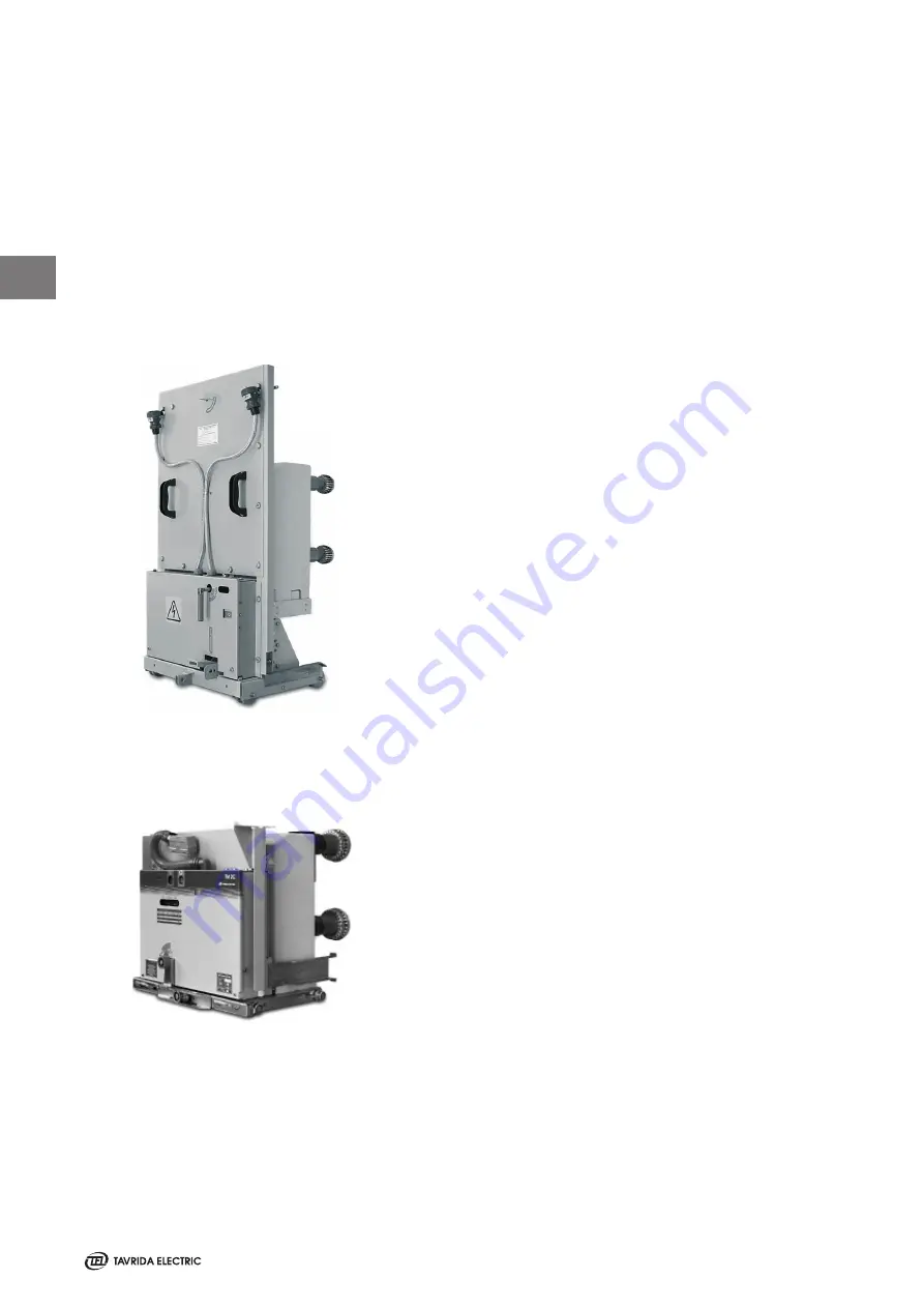
In any switchgear application, the ISM shall be installed with
the actuator drive axis vertical (Figure 16). ISM may be
installed in position “actuator up”, as well “actuator down”
(for all types).
The ISM shall be installed at the place designated for it on a
sufficiently stable frame. In order to prevent bending loads
at the support insulators the poles must be fixed as shown in
figure 20. The torque of all fixing points shall not exceed the
values stated in figure 20.
Vertical installation
position of the ISM (draw out type)
Vertical installation
position of the ISM (draw out type)
Figure 19
3
Summary of Contents for ISM Shell_2 Series
Page 2: ...2...
Page 6: ...6 1 THIS PAGE INTENTIONALLY LEFT BLANK...
Page 7: ...7 Introduction 1...
Page 12: ...12 1 THIS PAGE INTENTIONALLY LEFT BLANK...
Page 13: ...13 Receiving Handling and Storage 2...
Page 19: ...19 Ins tallation 3...
Page 36: ...36 3 THIS PAGE INTENTIONALLY LEFT BLANK...
Page 37: ...37 Switching and Control Functions 4...
Page 41: ...41 Commiss ioning Maintenance 5...
Page 44: ...44 5 THIS PAGE INTENTIONALLY LEFT BLANK...
Page 45: ...45 Signalling 6...
Page 49: ...49 Special Applications Fast Switching 6...
Page 53: ...53 Product Line 7...
Page 55: ...55 Dimens ions and Weights 8...
Page 61: ...61 8 Mating part with interlocking lever Interlockingshaftwithmountedinterlockinglever...
Page 62: ...62 Circuit Diagrams 9...
Page 63: ...63 ISM15_Shell_2 with CM_1501_01 9...
Page 64: ...64 ISM15_Shell_2 with CM_16_1 9...
Page 65: ...65 9 THIS PAGE INTENTIONALLY LEFT BLANK...
Page 66: ...66 Technical Data 10...
Page 71: ...71 10 THIS PAGE INTENTIONALLY LEFT BLANK...
Page 72: ...72 Regulations and Ambient Conditions 11...
Page 74: ...74 Legal Information 12...
Page 77: ...77 12 THIS PAGE INTENTIONALLY LEFT BLANK...
Page 79: ...79 Date 12...
Page 80: ...80 Date 12...
Page 81: ...81 Date 12...


