11
Closing
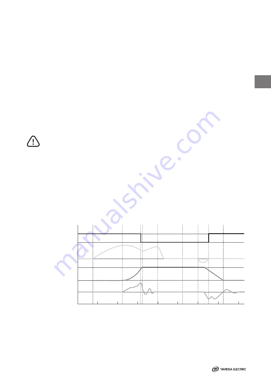
In the open position the contacts are kept open by the force of the opening springs. To close the contacts
the coils of the magnetic actuators are excited by a current impulse of the close capacitors of the CM. As a
result the contacts close. At the same time the opening springs are compressed. In the closed position the
contacts are kept closed by means of the magnetic force only. The ISM maintains the closed position
without mechanical latching also in case of a failure of the auxiliary power supply (Figure 5).
Opening
To open the contacts a current impulse in the reverse polarity derived from the opening capacitors of the
CM is injected in the coils of the magnetic actuators releasing the magnetic holding force. The compressed
opening springs and contact pressure springs open the contacts (Figure 5).
Manual-Emergency-Tripping
The ISM can be tripped mechanically without auxiliary power supply (emergency trip). It may be opened
manually by means of interlocking shaft rotating counter-clockwise. The interlocking cam of interlocking
shaft act on the armature, when then starts to move (refer to chapter “Installation/Primary part/
Interlocking”, page 24). As the air gap increases, the opening springs and contact pressure springs
overcome any magnetic holding force and the module opens.
Manual Closing
The ISM can only be closed electrically via the CM. In the case of a failure of auxiliary power supply the
contacts can be closed using an alternative auxiliary power supply such as a battery. Mechanical closing is
not possible and leads to the destruction of the ISM.
Position main
contacts
Actuator coil
current
Anchor travel
Anchor velocity
Open
Closed
Open
Closed
0
0
0
Close c
ommand CM (dr
y c
on
tac
t)
Close impuls t
o ISM
-c
oils
Star
t anchor mo
vemen
t
ISM main c
on
tac
ts closed
St
op anchor mo
vemen
t
Swit
ch off ac
tua
tor
cur
ren
t f
or close oper
ation
Tr
ip c
ommand CM
(dr
y c
on
tac
t)
Tr
ip impuls t
o ISM
-c
oils
ISM main c
on
tac
ts open
Open position kept b
y
opening spr
ings
0
20
40
60
80 100 120
140
160
Time (ms)
Figure 5
Typical oscillograms of ISM operation
1
Summary of Contents for ISM Shell_2 Series
Page 2: ...2...
Page 6: ...6 1 THIS PAGE INTENTIONALLY LEFT BLANK...
Page 7: ...7 Introduction 1...
Page 12: ...12 1 THIS PAGE INTENTIONALLY LEFT BLANK...
Page 13: ...13 Receiving Handling and Storage 2...
Page 19: ...19 Ins tallation 3...
Page 36: ...36 3 THIS PAGE INTENTIONALLY LEFT BLANK...
Page 37: ...37 Switching and Control Functions 4...
Page 41: ...41 Commiss ioning Maintenance 5...
Page 44: ...44 5 THIS PAGE INTENTIONALLY LEFT BLANK...
Page 45: ...45 Signalling 6...
Page 49: ...49 Special Applications Fast Switching 6...
Page 53: ...53 Product Line 7...
Page 55: ...55 Dimens ions and Weights 8...
Page 61: ...61 8 Mating part with interlocking lever Interlockingshaftwithmountedinterlockinglever...
Page 62: ...62 Circuit Diagrams 9...
Page 63: ...63 ISM15_Shell_2 with CM_1501_01 9...
Page 64: ...64 ISM15_Shell_2 with CM_16_1 9...
Page 65: ...65 9 THIS PAGE INTENTIONALLY LEFT BLANK...
Page 66: ...66 Technical Data 10...
Page 71: ...71 10 THIS PAGE INTENTIONALLY LEFT BLANK...
Page 72: ...72 Regulations and Ambient Conditions 11...
Page 74: ...74 Legal Information 12...
Page 77: ...77 12 THIS PAGE INTENTIONALLY LEFT BLANK...
Page 79: ...79 Date 12...
Page 80: ...80 Date 12...
Page 81: ...81 Date 12...


