HYDRAULIC CONTROL
ADJUSTMENT
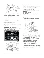
The hydraulic control link has been carefully adjusted in the
factory, so that adjustment is hardly ever necessary. However,
if
it is not working correctly, adjust it in the following manner:
When
carrying out this adjustment, stop and start the engine as
required.
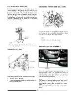
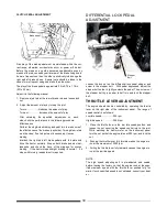
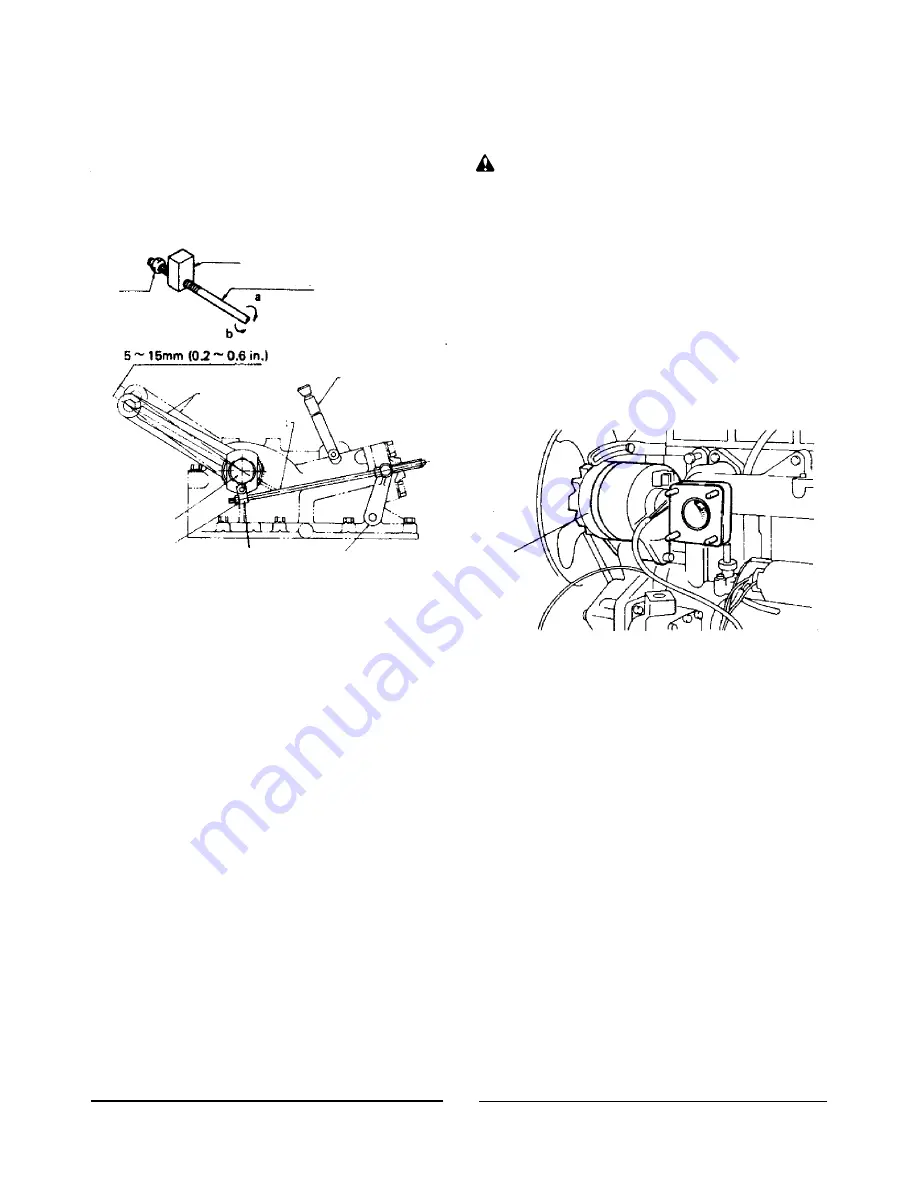
POSITION CONTROL
ADJUSTMENT
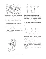
Joint
Nut
Feedback link
a: In case play is too small or not
available.
b: In case play is too great.
After adjustment, attach implement and raise engine speed
slightly (over 1500 rpm). Operate hydraulic control lever to
lift and lower the implement several times to check the func-
tion.
CAUTION
Be sure to check that there is no relief sound generated
after adjustment.
HYDRAULIC PUMP
RELIEF VALVE
The hydraulic system is equipped with a pump relief valve to
protect the hydraulic pump and pipe line against accidents
caused by high hydraulic pressure in the system.
The set pres-
sure is 135 kg/cm
2
(1920 psil at full flow). Never disturb nor dis-
assemble the pump relief valve since its adjustment requires
special tools and instruments.
Lift arm
Position control
lever
ALTERNATOR
Feedback link
Hydraulic Shaft
Nut
Joint
Arm
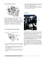
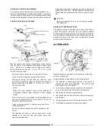
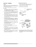
Start the engine, and operate the hydraulic control lever to
raise the lift arm to the maximum lifting position without imple-
ment. With the arm so raised, stop the engine, and check to
be sure that there is a play of 5 ~ 15 mm ( 0.2 ~ 0.6 in. ) at the
top of the lift arm by hand.
Move stop lever on lifting end all the way and fix it there.
Have a lift rod for implement removed off the lift arm.
With engine running at about 1000 rpm, raise the control
lever until it contacts the stopper and check the amount of
play at lift arm end to be about 5 ~ 15 mm ( 0.2 ~ 0.6 in. )
with
the lift arm lifted.
NOTE
Without this play, hydraulic circuit will be subjected to
unnecessary pressure when implement is lifted, causing
trouble.
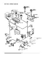
If play is too small or not available, loosen feedback link nut
and turn the feedback link to the direction of lift arm for
adjustment (tightening direction).
If play is too great, adjust It in direction away from lift arm
(loosening direction).
Be sure to lock the feedback link nut after adjustment with-
out fail.
The feedback link which is used for depth control is also
adjusted to the same free play with position control feed-
back link described above.
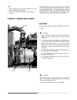
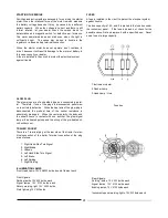
Alternator
Sealed bearings are employed for this alternator, so that lubri-
cation is not necessary.
During maintenance, pay attention to the following points.
1.
The alternator is negative-grounded and if the polarity is
reversed, the diode will be damaged. Be careful enough
when connecting it to the battery.
2.
As the battery voltage is always connected to the terminal
A,
never run the engine with the terminal
A
disconnected.
3.
Don't water the alternator at high pressure.
4.
Pay full attention to the belt tension so that normal charging
may be made.
5.
During operation, be sure to set the starter switch at "ON".
6.
If difficulties are experienced, consult your dealer.
40
Summary of Contents for VST 818
Page 2: ......
Page 16: ...SECTION 2 EXTERNAL VIEW AND NOMENCLATURE OF EACH PART The above photos show TARAL VST 818 6 ...
Page 35: ...25 ...
Page 36: ...GREASING DIAGRAM Greasing Nipple Greasing Nipple Greasing Nipple 26 ...
Page 45: ...PROPER BATTERY MAINTENANCE AND TIPS FOR SAFETY 35 ...
Page 53: ...SECTION 8 WIRING DIAGRAM 43 ...
Page 58: ......
Page 59: ......

