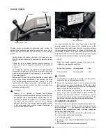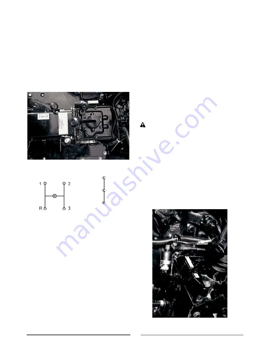
8-SPEED TRANSMISSION
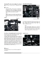
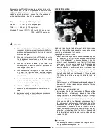
The gear shift positions are as shown in the diagram below.
By combination of the Main and High-Low shift levers, six for-
ward speeds and two reverse speeds can be obtained.
The
first, second, and third forward speeds and first reverse speed
can be obtained with High-Low shift lever in the LOW position,
and
the fourth,
fifth, and sixth forward speeds and second
reverse
speed can be obtained with the High-Low shift lever in
the HIGH
position.
4-WHEEL
DRIVE SHIFT LEVER
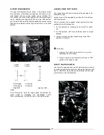
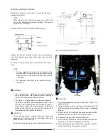
The 4-wheel drive shift lever is located on the right side of the
transmission case.
4-wheel drive will be engaged by pushing the 4-wheel drive
shift lever forward.
With the 4-wheel drive engaged, proper power will become
available for the following cases:
1.
For the operation on inclined ground, wet field or sandy
soil.
2.
For the operation with front end loader, trailer or plough
attached.
3.
In
order to prevent lunging forward during rotary tilling
operation on hard soil.
CAUTION
1.
Operate the 4-wheel drive shift lever only after
depressing the clutch pedal.
2.
Be sure to place the 4-wheel drive shift lever in "OFF"
position for travelling on road.
1. speed
4. speed
2. speed
5. speed
LOW
SAFETY
STARTER SWITCH
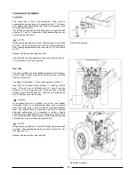
The
Tractor is equipped with a safety starter switch to prevent
an accident in starting the engine. By placing the High-Low shift
lever in NEUTRAL, the speed can be obtained with the High-
Low shift lever in the HIGH position
HIGH
R 1st Speed
3rd Speed
R 2nd Speed
6th Speed
Main Shift
High-Low Shift
NOTE
To shift the gears-, lower the engine speed and depress the
clutch
pedal
to
disengage
the
transmission
clutch.
When
reversing gear, first stop the tractor, then shift the gears.
13
Summary of Contents for VST 818
Page 2: ......
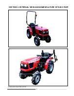
Page 16: ...SECTION 2 EXTERNAL VIEW AND NOMENCLATURE OF EACH PART The above photos show TARAL VST 818 6 ...
Page 35: ...25 ...
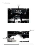
Page 36: ...GREASING DIAGRAM Greasing Nipple Greasing Nipple Greasing Nipple 26 ...
Page 45: ...PROPER BATTERY MAINTENANCE AND TIPS FOR SAFETY 35 ...
Page 53: ...SECTION 8 WIRING DIAGRAM 43 ...
Page 58: ......
Page 59: ......

