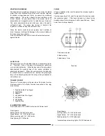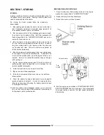
CLUTCH PEDAL
ADJUSTMENT
DIFFERENTIAL
LOCK PEDAL
ADJUSTMENT
Brake pedal
Free play of the brake pedal must be maintained within the cor-
rect range, otherwise, accident may occur or power will be lost.
Before the brake on one side becomes unadjustable even by
means of the rod, caused by earlier wear of the brake lining due
to
its more frequent use than the other, periodically interchange
the
right and left brake shoes. Special care should be taken in
the
case of more frequent using one brake than the other.
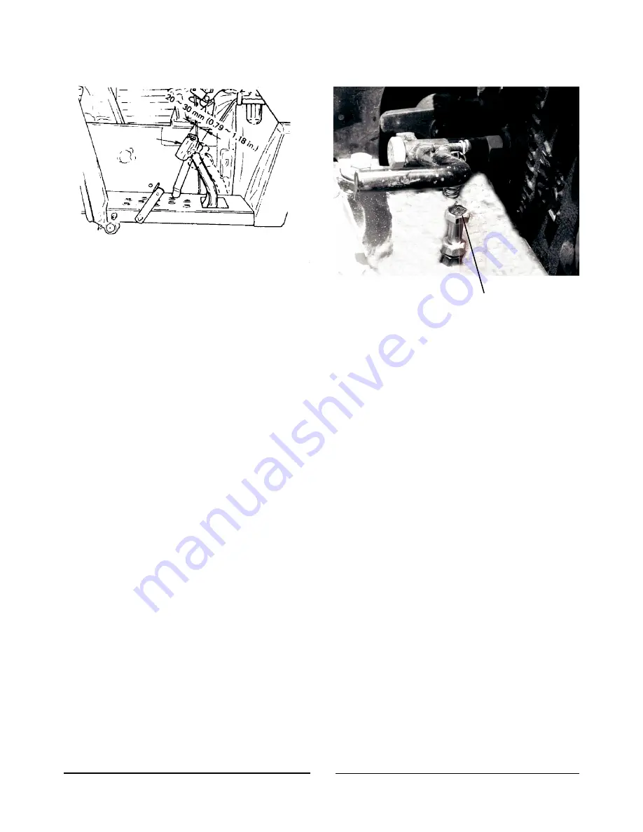
The play of the brake pedal is appropriate if it is 0.79 to 1.18 in.
(20 to 30 mm).
Adjust it in the following manner:
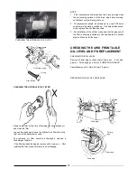
1. Remove a joint pin at the rear of brake rod, and loosen lock
nut.
2.
Adjust the amount of play by turning the joint.
Turn-in……….........Reduces the amount of play
Turn-out……………Increases the amount of play
After
obtaining
the
specified
dimensions
on
each
side,
check the performance in the following procedure:
Effectiveness
Perform the single-side braking and pivot turn to make sure
of
the effectiveness of the brakes (each side).
Turning diam-
eters
must be close; if not, adjustment is necessary.
Uneven
braking
Interlock the right and left brake pedals with link plate and
drive the tractor normally. Step on both brake pedals simul-
taneously and check the trace of tire slippage for uneven
braking. If the tractor stops straight, braking is normal. If it
stops with turning, readjustment is required.
Stopper
Bolt
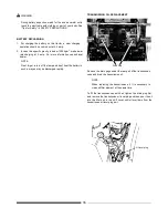
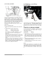
Loosen the lock nut on the differential lock pedal stopper, and
screw in the stopper bolt. With pedal depressed, adjust the
stopper bolt so that it lightly contacts the pedal.
Then, screw out
the stopper bolt by a quarter to half turn and lock the stopper
bolt.
THROTTLE LEVER
ADJUSTMENT
The engine speed can be controlled by operating the throttle
lever on the right side of the instrument panel.
The range of
speed control is as follows:
Low idle speed……........…900 rpm
High idle speed……………2900 rpm
1.
Place the throttle lever in the low idle speed position, and
loosen the nut securing the speed control rod to the joint.
While watching the tractor meter on the instrument panel,
turn the nut so that the engine idles at 900 rpm, and lock the
nut.
2.
Pushing the throttle lever fully forward makes the engine to
run at the maximum of 2900 rpm.
3.
Pulling the throttle lever fully rearward causes the engine to
run at the low idle speed.
NOTE
The high speed adjusting bolt is pre-adjusted and sealed,
before leaving the factory, so that the engine runs at the spec-
ified maximum speed with the throttle lever pushed fully for-
ward.
If such specified speed is not obtained, consult your deal-
er.
39
Summary of Contents for VST 818
Page 2: ......
Page 16: ...SECTION 2 EXTERNAL VIEW AND NOMENCLATURE OF EACH PART The above photos show TARAL VST 818 6 ...
Page 35: ...25 ...
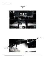
Page 36: ...GREASING DIAGRAM Greasing Nipple Greasing Nipple Greasing Nipple 26 ...
Page 45: ...PROPER BATTERY MAINTENANCE AND TIPS FOR SAFETY 35 ...
Page 53: ...SECTION 8 WIRING DIAGRAM 43 ...
Page 58: ......
Page 59: ......

