5.
Treat antifreeze carefully so that it may not remove paint
from the cylinder block.
6.
Any antifreeze solution (antifreeze and water), even if it is
permanent antifreeze, should not be used for more than 2
years.
7.
Confirm that there are no leak from the hose connections or
cylinder head gasket.
8.
Antifreeze with proper density to suit the climate in your
area should be used.
9.
When antifreeze is used over a long period in winter, mea-
sure the specific gravity frequently.
NOTE
Consult your dealer concerning detergent and antifreeze.
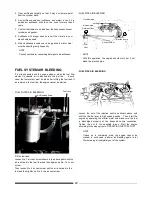
FUEL
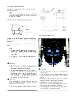
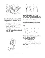
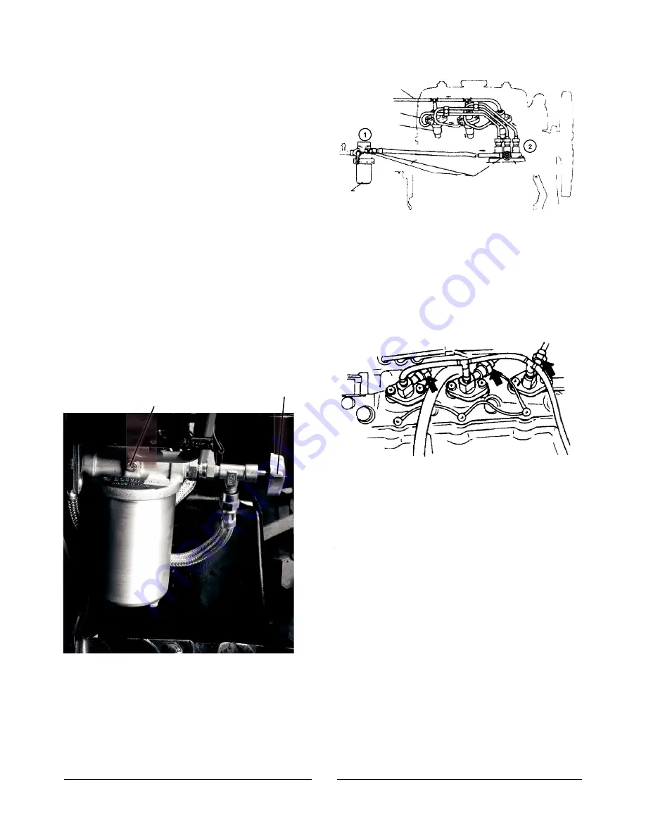
PIPE AIR
BLEEDING
Overflow pipe
Injection pipe
Nozzle holder
Air vent screw
Fuel
filter
NOTE
Injection pump
With this operation, the engine should start, but if not,
bleed the injection pipe.
FUEL
SYSTEM AIR
BLEEDING
If fuel is exhausted and the engine stops or when the fuel filter
element is cleaned, air is induced into the fuel line. In such
case, the fuel system must be bled after refilling the fuel tank.
If
air remains in the fuel line, the engine cannot be started.
FUEL
PIPE AIR
BLEEDING
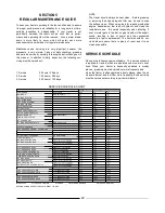
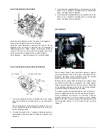
FUEL
FILTER AIR
BLEEDING
Air Bleeding Screw
Fuel cock
Loosen the nut of the injection nozzle as shown above and
shift the throttle lever to high speed position.
Then, start the
engine by operating the starter motor and make sure the fuel
is discharged properly at the loosened nozzle connection.
Tighten the nut to the specified torque. Start the engine
according to the steps given in "OPERATING
THE
TRACTOR".
NOTE
Unless air is completely bled, the engine cannot be
started; in such case, perform air bleeding again to let
the
remaining air completely out of the system.
Fill the fuel tank.
Loosen No. 1 air vent screw shown in the above photo until no
air is noticed in the fuel flow and then tighten up No. 1 air vent
screw.
Then loosen No. 2 air vent screw until no air is noticed in the
fuel and then tighten up No. 2, the air vent screw.
29
Summary of Contents for VST 818
Page 2: ......
Page 16: ...SECTION 2 EXTERNAL VIEW AND NOMENCLATURE OF EACH PART The above photos show TARAL VST 818 6 ...
Page 35: ...25 ...
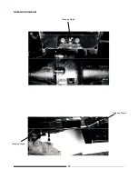
Page 36: ...GREASING DIAGRAM Greasing Nipple Greasing Nipple Greasing Nipple 26 ...
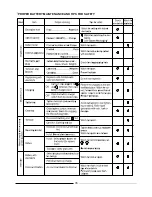
Page 45: ...PROPER BATTERY MAINTENANCE AND TIPS FOR SAFETY 35 ...
Page 53: ...SECTION 8 WIRING DIAGRAM 43 ...
Page 58: ......
Page 59: ......

