26
Chapter
1
Controls and Indicators
MENU/ENTER
While in offline mode, this key allows entry into the configuration menus.
When navigating the configuration menus, MENU/ENTER selects the
currently displayed option value as the active value. An asterisk (*)
appears next to the active value on the display. MENU/ENTER is also
used for starting and stopping printer tests and generating a configuration
printout.
9
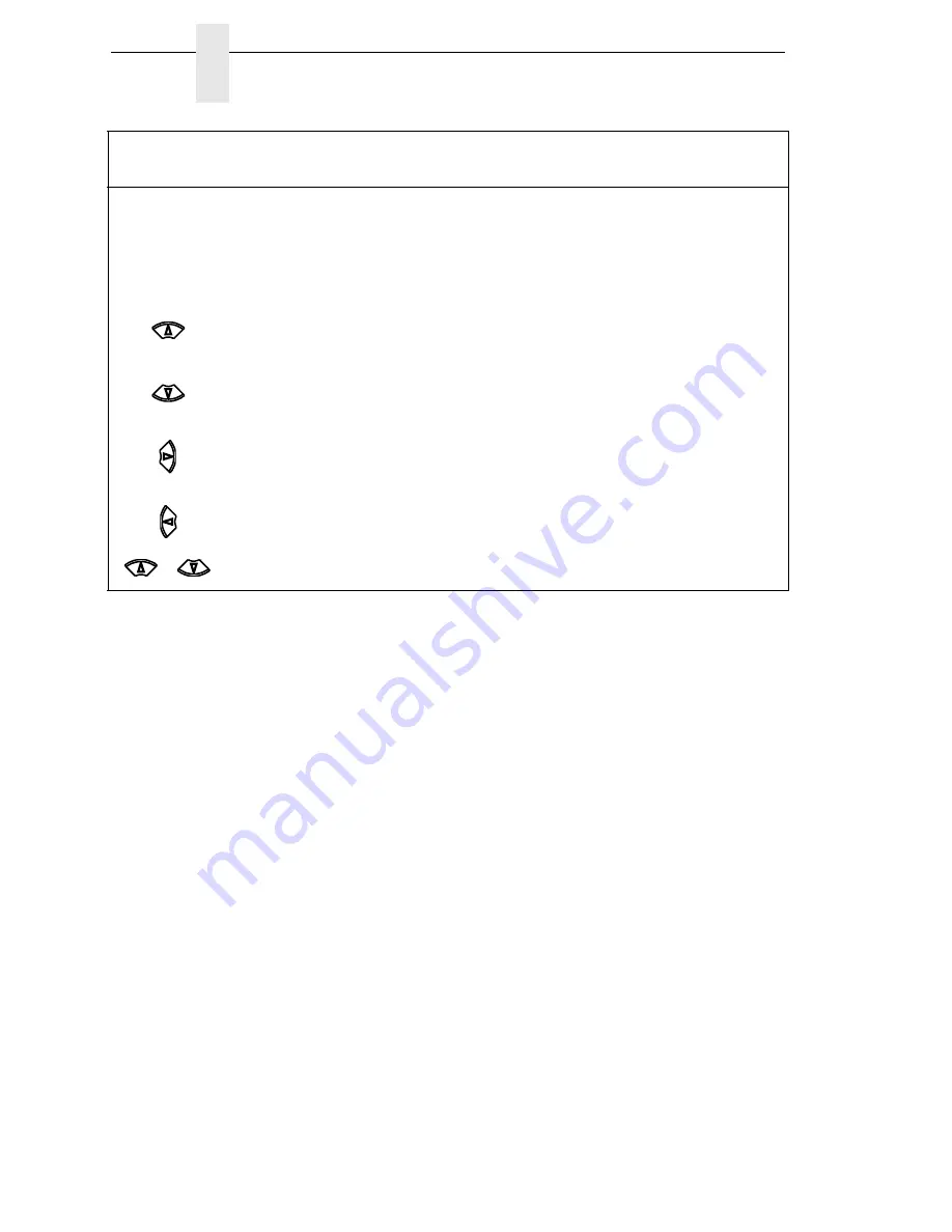
Moves up between levels in the configuration menus. When in offline
mode, makes vertical forms adjust.
In VIEW mode, moves paper up 1/72 inch. (See VIEW key.)
9
Moves down between levels in the configuration menus. When in offline
mode, makes vertical forms adjust.
In VIEW mode, moves paper down 1/72 inch. (See VIEW key.)
9
Moves between the options on the current level of configuration.
9
Moves between the options on the current level of configuraiton.
9
+
Press up and down arrow keys together unlocks or locks the MENU/
ENTER key.
9
Switch or
Indicator
Function
Active
Online
Active
Offline
Summary of Contents for 6600 Series
Page 1: ...6600 Series Printers Maintenance Manual Approved Final May 19 2011 ...
Page 2: ......
Page 3: ...6600 Series Printers Maintenance Manual ...
Page 10: ......
Page 34: ...34 Chapter 1 Maintenance Training for TallyGenicom Products ...
Page 42: ...42 Chapter 2 Cleaning the Card Cage Fan Assembly ...
Page 265: ...Illustrations of Printer Components 265 Parts lists continue on the next page ...
Page 278: ...278 Chapter 6 Organization of this Chapter ...
Page 300: ...300 Chapter 7 Printer Interface ...
Page 305: ...305 Cable Routing Pedestal Model 184043a Exhaust Fan Weld Sensor Cable ...
Page 320: ...320 Appendix A Cable Assembly 2 Pin Jumper 0 1 Ctr P N 154470 901 ...
Page 323: ...323 Cable Assy PS I O P N 176601 901 NOTE This cable is used on 6620 and 6620Q printers ...
Page 324: ...324 Appendix A Cable Assembly Card Cage Fan P N 152422 901 PIN 1 PIN 1 ...
Page 325: ...325 Cable Assembly Control Panel P N 152440 901 PIN 1 PIN 1 PIN 8 PIN 8 Gray Brown Gray Brown ...
Page 326: ...326 Appendix A Cable Assembly Exhaust Fan P N 152424 901 PIN 1 PIN 1 ...
Page 327: ...327 Cable Assembly Hammer Bank Logic P N 152421 901 To Shuttle To Controller Board ...
Page 330: ...330 Appendix A Cable Assembly MPU P N 152425 901 PIN 1 PIN 3 PIN 2 PIN 1 ...
Page 331: ...331 Cable Assembly Ribbon Motor Extension P N 154067 001 ...
Page 332: ...332 Appendix A Cable Assembly Shuttle Motor Drive P N 152420 001 ...
Page 333: ...333 Frame Cable Power Stacker P N 173824 001 ...
Page 334: ...334 Appendix A Logic Cable Power Stacker P N 176029 001 ...
Page 335: ...335 Power Cable Power Stacker P N 174414 001 P1101 P1101 ...
Page 336: ...336 Appendix A Rail Cable Power Stacker P N 173823 001 ...
Page 337: ...337 Elevator I O Cable Power Stacker P N 174759 001 ...
Page 338: ...338 Appendix A Fan Assembly Hammer Bank P N 152416 901 P107 HBF P107 HBF ...
Page 339: ...339 Magnetic Pickup MPU Assembly P N 150281 901 ...
Page 340: ...340 Appendix A Switch Assembly Paper Detector P N 152415 901 ...
Page 341: ...341 Switch Assembly Platen Interlock P N 152417 901 P107 PLO ...
Page 342: ...342 Appendix A ...
Page 402: ...402 Appendix D Illustrated Parts Breakdown ...
Page 448: ...448 Appendix E Illustrated Parts Lists ...
Page 460: ...460 Appendix F Summary ...
Page 472: ...472 ...
Page 473: ......
Page 474: ... 255559 001 255559 001A Approved Final May 19 2011 ...


