


TR
OUBLE SHOO
TING
On-Demand Water Heater Installation Manual and Owner’s Guide
73
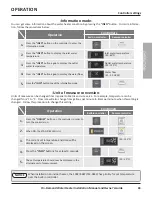
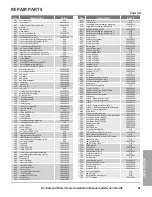
The following list contains error codes, their descriptions, and items to check. If you are not qualified or com-
fortable performing any of the checks below, contact a qualified service agent or the manufacturer’s Technical
Assistance Line. The phone number is located on the front cover of this manual.
Remote Green
LED
Malfunction
description
Diagnosis
031
One
Flash
Incorrect DIP
switch setting
• Check the DIP switch settings on the PCB (Part #701).
051
Three
Flashes
Insufficient com-
bustion air and gas
• Check for dust and dirt on the air screen of the rain protection tray (Part #007)
and verify air intake is not blocked.
• Check for connection/breakage of wires (Part #123, 715), burn marks on the
computer board (Part #701).
101
Five
Flashes
Combustion air
and exhaust air
blockage warning
• See 991 Error Code.
111/
121
Three
Flashes
Ignition failure/
Loss of flame
• Check if the Hi-limit switch (Part #412) is functioning properly. The switch has a
button in its center, pressing the button will reset the switch. If tripped, you will hear
and feel it click when resetting. If the high limit switch continues to trip contact a
qualified service technician.
• Check for connection/breakage of wires, burn marks on the computer board (Part
#701), and/or soot on the flame rod (Part #108).
• A “buzzing” ignition sound should be coming from the burner (Part #101) when the
water heater prepares for combustion, if not heard then the igniter (Part #710) may
be the issue.
• Listen for the “clunk” sound coming from gas solenoid valve assembly (Part #130)
when water heater goes into combustion. If nothing is heard, then check the hi-limit
switch (Part #412), overheat-cut-off fuse (Part #413) and connections to the gas valve
Part #102).
• Check if there is water leaking from heat exchanger (Part #401) onto the flame and/
or igniter rods (Part # 108, 109).
201
One
Flash
Combustion air
and gas line failure
• Check if the Hi-limit switch (Part #412) is functioning properly. The switch has a
button in its center, pressing the button will reset the switch. If tripped, you will hear
and feel it click when resetting. If the high limit switch continues to trip contact a
qualified service technician.
• Check if the fan motor (Part #103) is functioning properly.
• Check for connection/breakage of wires, burn marks on the computer board (Part
#701).
211
Three
Flashes
Pressure sensor
failure
• Check for connection/breakage of wires (Part #123, 715), burn marks on the
computer board (Part #701).
311
Two
Flashes
Heat exchanger
thermistor failure
• Check for connection/breakage of wires and/or debris on thermistor (Part
#407, 408, 411, 715, 718, 731).
321
Two
Flashes
Inlet thermistor
failure
331
Two
Flashes
Outlet thermistor
failure
341
Two
Flashes
Exhaust thermistor
failure
351
Two
Flashes
Return Thermistor
Failure
TROUBLE SHOOTING
Fault analysis
Fault analysis
Summary of Contents for 160X3P
Page 84: ...7J8071 1 2000570774 REV B...


