background image

INS
TALLA
TION

On-Demand Water Heater Installation Manual and Owner’s Guide 

19

Determine type of ventilation

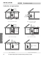
There are several types of ventilation that can be used.  The various options are listed below.  See also the illustra-

tions on the next page.

1.  Direct to outdoors (See Figures 1&2)
2. 

Vertical ducts (See Figure 3)

3.  Horizontal ducts (See Figure 4)
4.  Single opening  (not recommended; must be at least 100 in

2

 (645 cm

2

) .  Not appropriate for confined spaces smaller 

than 50 ft

3

 (1.42 m

3

) per 1,000 BTU/h or when getting air from another room.) See Figure 5.

5.  From a larger room inside the house (not recommended – refer to "Calculate the air volume of the room" on page 18 to 

determine if the combined volume of the rooms may be adequate).

Determine minimum free area required for each vent opening

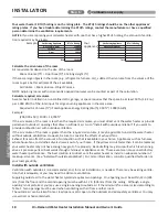
The size of the vent openings depends on the total BTU/h rating of all appliances in the space (use your calculation 

from “Before beginning”) and the type of vent used.  Table 1 provides the minimum free area for each vent opening 

depending on the type of ventilation.

Calculate minimum size of vent openings and ducts

The vent cross-sectional area needed to provide the free area depends on the covering on the vent openings.  

Typical vents use louvers or grilles to protect the opening.  The louver or grill itself blocks some of the free area, so 

the opening may need to be larger to meet the minimum free area requirements.  

Use the following formula to calculate the required cross-sectional area:

Cross-sectional area = minimum free area required ÷ percent free area of covering (in decimals – e.g., 60 % = 0.6)

For example, an installation area that requires openings with 100 in

2

 (645 cm

2

) of free area would need 134 in

2

 (865 

cm

2

) openings if using metal louvers rated at 75% free area (100 in

2

 ÷ 0.75 = 134 in

2

).

If you do not know the % free area for your louver or grill, use the following values:

• 

For wood louvers or grilles: 25%

• 

For metal louvers or grilles: 75%

Follow these rules to ensure that vents and ducts provide adequate air flow:

•  Each vent opening must  be no smaller than 100 in

2

 (645 cm

2

).

• 

Ducts must have the same  cross-sectional area as free area of the opening.

•  Rectangular ducts must have a minimum dimension of no less than 3 in (76 mm).

•  All screens must have mesh ¼” or larger.

• 

Moveable louvers must be locked open or interconnected with the equipment so that they open automatically during 

operation.

• 

Keep louvers and grills clean and free of debris or other obstructions.

Check that air source is clean and free of chemicals

Air for combustion and ventilation must be clean and free of corrosive or flammable chemicals.  A failure due to corrosive chemi

-

cals in the air is not covered by the warranty.  Combustion air must be free of acid-forming chemicals such as sulfur, fluorine, and 

chlorine.  Be sure that air at the vent inlets is free of such chemicals.

See graphics on next page.

Table 1

Minimum Free Area of Permanent Openings for Ventilation and Combustion Air Supply – Air from outdoor or indoor spaces.

Based on the total BTU/h input rating for all gas burning appliances within a confined space.

Opening Source

Minimum Free Area

Direct to outdoors*

in

2

 (6.5 

cm

2

) per 4,000 BTU/hr (see Figure 

1, 2

)

Vertical ducts

in

2

 (6.5 

cm

2

) per 4,000 BTU/hr (see Figure 

3

)

Horizontal ducts

in

2

 (6.5 

cm

2

) per 2,000 BTU/hr (see Figure 

4

)

Single Opening

in

2

 (6.5 

cm

2

) per 3,000 BTU/hr (see Figure 

5

)

Two permanent openings  

to another room**

in

2


(6.5 

cm

2

) per 1,000 Btu/hr


(see Figure 

6

Opening: 100 in

(645 cm

2

) Min   

Minimum dimension of air openings: no less than 3 in (76 mm)

*These openings connect directly with the outdoors through a ventilated attic, a ventilated crawl space, or through an outside wall.

**United States: For direction on combining spaces in different stories within the structure, refer to the current edition of the 

National Fuel Gas Code ANSI Z223.1/NFPA 54.  In Canada, contact your local code enforcement agency for direction.

INSTALLATION

Step  6:

Combustion air supply

Summary of Contents for 160X3P

Page 1: ...manual near the water heater for future reference whenever maintenance adjustment or service is required Do not store or use gasoline or other flammable vapors and liquids in the vicinity of this or...

Page 2: ...bustion status 35 CO2 value 35 12 Water connections 36 Recirculation pump modes 37 Standard recirculation 38 Standard non recirculation 38 Recirculation with cross over valve 39 Installation w o recir...

Page 3: ...nual carefully Keep this manual for future reference If you need an additional manual contact the manufacturer or your local distributor You may also download a manual from our website When you call p...

Page 4: ...ural Gas Input Operating Range BTU h Min 9 000 Max 160 000 Min 9 000 Max 180 000 Min 9 000 Max 199 000 Propane Input Operating Range BTU h Min 9 000 Max 160 000 Min 9 000 Max 180 000 Min 9 000 Max 199...

Page 5: ...1 DRAIN 2 1 4 56 5 GAS 5 3 8 136 9 COLD GAS DRAIN RETURN PRV HOT 5 15 16 151 3 COLD 4 1 2 115 HOT 2 3 8 60 7 PRV 4 5 8 116 7 3 3 8 85 1 4 5 8 118 1 5 7 16 137 6 6 152 11 3 4 298 3 29 13 16 756 8 28 5...

Page 6: ...ed NOTICE Indicates an imminently hazardous situation which if not avoided will result in death or serious injury DANGER Indicates an imminently hazardous situation which if not avoided could result i...

Page 7: ...ated as it circulates through the heat exchang ers 7 Thermistors measure water temperatures throughout the water heater the control modulates the gas and water valves to ensure proper output water tem...

Page 8: ...mounted to a wall or other suitable structure Failure to observe these warnings could result in severe personal injury death and or property damage NOTICE The warranty will not cover damage caused by...

Page 9: ...e powders including flour can clog the air intake and reduce the operation of the fan This in turn can cause improper combustion and reduce the life of the water heater Regularly ensure that the area...

Page 10: ...1ft 30cm min Canada 3ft 91cm min USA 1ft 30cm min Canada 3ft 91cm min USA 12 in 30 cm above grade and above anticipated snow level Canada 12 in 30 cm above grade Anticipated snow level Ensure that yo...

Page 11: ...e of the installation The pipe cover or recess box is recommended when the water heater is installed outside Neutralizer kit 100112159 TH NT01 Used to raise the pH of the condensate to allow for safe...

Page 12: ...of the National Fuel Gas Code ANSI Z223 1 NFPA 54 in the United States and or Section 8 of the B149 1 Natural Gas and Propane Installation Code in Canada as well as applicable local building codes Ref...

Page 13: ...el the bracket Wall Stud Wall Stud 16 406 4 mm Drywall cut away to show proper method to mount the bracket to the wall studs 2 Hang the water heater bracket on the wall bracket 3 Secure the water heat...

Page 14: ...r model Vertical venting roof termination is acceptable The manufacturer recommends running the exhaust vent and the intake pipe as parallel as possible For rooftop venting a rain cap or other form of...

Page 15: ...r death 2 Use a screwdriver to tighten the clamp Figure 2 3 Use the supplied self tapping screws to secure the venting to the intake and exhaust ports as shown in the image on the right Figure 3 For 3...

Page 16: ...9 ft 1 5 to 3 0 m Exhaust 2 PV Intake 2 elbow 5 ft 1 5 m Exhaust 5 to 14 9 ft 1 5 to 4 5 m 3 DV Intake 5 to 59 9 ft 1 5 to 18 3 m Exhaust 3 PV Intake 2 elbow 5 ft 1 5 m Exhaust 5 to 59 9 ft 1 5 to 18...

Page 17: ...corrosive chemicals are not present at the air intake Presence of such chemicals at the air intake could result in death personal injury or property damage Examples of locations that require outside a...

Page 18: ...cient air Go to Install with outside ventilation if you want to provide combustion air with outside ventilation If the air volume of the room is greater than the required air volume it may be possible...

Page 19: ...od louvers or grilles 25 For metal louvers or grilles 75 Follow these rules to ensure that vents and ducts provide adequate air flow Each vent opening must be no smaller than 100 in2 645 cm2 Ducts mus...

Page 20: ...cm2 per 4 000 btu h Con ned Space 12 305mm maximum Gable vent to outdoors Install above insulation Figure 5 SIngle opening Con ned Space 1 in2 6 5 cm2 per 3 000 btu h Alternative Opening Location Fig...

Page 21: ...heater as possible This is to drain any water that may be in the combustion air pipe and prevent it from entering the water heater The drain tubing in any installation should have a loop trap and flow...

Page 22: ...of the National Fuel Gas Code ANSI Z223 1 NFPA 54 Item Material United States Canada Exhaust pipe and Fittings Schedule 40 PVC ANSI ASTM D1785 ULC S636 Certified Materials Only PVC DWV ANSI ASTM D266...

Page 23: ...Direct Vent installation examples INSTALLATION Horizontal Installation Hanger Roof flashing Fire stop Vertical Installation 2 Power Vent installation examples Vertical Installation Roof flashing Fire...

Page 24: ...1738 PVC Part Number 2 Low Profile Term 100187903 196984 397984 3 Low Profile Term 100187887 196985 397985 Concentric termination B A C A B C FGV 2 29 16 2 FGV 3 36 20 3 Vent Pipe Size PVC Kit Number...

Page 25: ...INSTALLATION On Demand Water Heater Installation Manual and Owner s Guide 25 INSTALLATION This page is intentionally blanked...

Page 26: ...side of opening 1 ft 30 cm above opening K Clearance to mechanical air supply inlet 6 ft 183 cm 3 ft 91 cm above if within 10 ft 3 m horizontally L Clearance above paved sidewalk or paved driveway loc...

Page 27: ...vent sidewall terminations that use two separate penetrations for the intake and exhaust keep the termination clearances shown in the diagrams below Improper installation can result in carbon monoxide...

Page 28: ...re to observe this warning may result in severe personal injury or death WARNING Multiple flat roof terminations Canadian requirements differ from the guidelines in this section In Canada follow the r...

Page 29: ...eater as shown in the following figure Attach the vent cap to the top of the water heater in the orientation shown below securing it with the four screws removed in the previous step Be sure to insert...

Page 30: ...ront cover of the water heater Use the figure below as a reference for exact placement Do not attach the operation panel cover directly to the built in controller NOTE Remove the front cover to operat...

Page 31: ...e water heater s minimum to maximum input and provide the specified pressures that are listed on the rating plate In the absence of minimum install distance stated by the regulator manufacturer it is...

Page 32: ...32 590 504 448 409 378 346 322 307 275 252 213 1 1 4 2 205 1 496 1 212 1 039 913 834 771 724 677 630 567 511 440 1 1 2 3 307 2 299 1 858 1 559 1 417 1 275 1 181 1 086 1 023 976 866 787 675 2 6 221 4 3...

Page 33: ...ied service agency is any individual firm corporation or company which either in person or through a representative is engaged in and is responsible for the connection utilization repair or servicing...

Page 34: ...Verify that the gas supply pressure is within an acceptable range Refer to Gas Supply and Gas Pipe Sizing for Propane on p 31 15 After the water heater has been installed and the gas line pressure te...

Page 35: ...g down the MIN button turn the screw clockwise to increase or turn the screw counterclockwise to decrease the CO2 value and fall into the range of CO2 value in the table below with the driver See Figu...

Page 36: ...water supply using 3 4 inch National Pipe Thread NPT to the fitting marked C COLD For ease of removing the water heater for service or replacement connect the water pipes with a coupling called a uni...

Page 37: ...See p 60 to set the Pump Timers 2 On Demand Mode In this mode the pump will only activate when the user pushes the Pump button on the heat er s built in controller or accessory remote controller See...

Page 38: ...water line and return line Please refer to the diagram below Check valves aren t necessary for the crossover install Insulate the hot water supply line and dedicated return line to prevent heat loss...

Page 39: ...VIEW X3 CARTRIDGE NOT SHOWN FOR CLARITY EXPANSION TANK CROSS OVER VALVE DOES NOT COME WITH THE WATER HEATER COLD WATER SUPPLY EXPANSION TANK Y STRAINER SIDE VIEW X3TM CARTRIDGE NOT SHOWN FOR CLARITY...

Page 40: ...move the metal fastener on Joint D and detach the plug Reattach the plug to Joint F Attach the metal fastener to secure the connection at Joint F NOTICE The plug MUST be installed into Joint F DO NOT...

Page 41: ...t be capped NOTICE Use this method when recirculation is not used such as when the return line will be installed later Before the water heater is put into service ensure that no timers are set to acti...

Page 42: ...water conditions may impact the efficiency of X3 such as excessive iron or manganese levels Refer to the guidelines below and consult a water quality expert to determine if your water is within accept...

Page 43: ...ve The pressure relief valve must be manually operated periodically to check for correct operation Before operating the valve manually check that it will discharge in a place for secure disposal No va...

Page 44: ...freely with gravity only Ensure that the condensate drain tube is not plugged or blocked and ensure that it slopes downward to allow condensate to flow freely All portions of the condensate drain neut...

Page 45: ...hould be plugged into a 120VAC 60 HZ elec trical outlet Cut plug here Power Cord Junction Box Conduit Connector Conduit WHITE BLACK BARE COPPER WHITE BLACK GREEN ELECTRICAL JUNCTION BOX WITH DISCONNEC...

Page 46: ...ater When installed the remote will take priority over the built in controller of indoor models Installation This remote controller is NOT waterproof The water heater can only have one remote controll...

Page 47: ...th the screws No polarity Do NOT jump or short circuit the cable or the computer will be damaged 7 Replace the front cover 8 Reconnect power supply to the water heater For outdoor installation Insert...

Page 48: ...IP switch positions 0 to 2 000 ft 0 to 610 m DEFAULT 2 000 to 3 000 ft 611 to 914 m 3 000 to 5 000 ft 915 to 1 524 m 5 000 to 7 500 ft 1 525to2 286m 7 500 to 10 100 ft 2 287to3 078m Middle bank of DIP...

Page 49: ...rately to minimize the amount of cold air entering through the exhaust venting when the water heater is off It is the installer s and owner s responsibility to be aware of freezing issues and take all...

Page 50: ...e designated as a PARENT unit by changing the Parent Child DIP switch Refer to the procedure below The other unit s are CHILD units Hot Out Gas In Cold In Return Line Each CHILD unit is allocated the...

Page 51: ...is the PARENT unit the only controller that can be used is the 100276687 TM RE43 3 Select a 160X3P 180X3P 199X3P unit to be the PARENT unit The PARENT unit should be one of the end units 4 On the PARE...

Page 52: ...for the presence of leaking gas toward the bottom of the unit because some gases are heavier than air and may settle towards the floor Check the GAS PRESSURE Refer to p 31 Do not try to light the burn...

Page 53: ...D BY LED turns off or Press and hold INFO and PUMP simultaneously for at least three sec onds then the integrated pump starts operation for five minutes or A segment of the zero is lighting as follows...

Page 54: ...d Owner s Guide Initial Operation cont 9 After finishing the pump operation test complete the following procedures Refer to pp 58 to 62 Set outlet water temperature Setting the time Pump operation tim...

Page 55: ...empted repair may result in a fire or explosion D Do not use this appliance if any part has been under water Immediately contact a qualified installer or service agency to replace a flooded water heat...

Page 56: ...er 2 In approved containers 3 Tightly closed and 4 Out of reach of children Vapors 1 Cannot be seen 2 Are heavier than air 3 Go a long way on the floor 4 Can be carried from other rooms to the main bu...

Page 57: ...tton or the COLD button to set the outlet water tem perature the current time and PUMP TIMER 6 LCD The current time set temperature error code and other information are displayed 3 COLD Button 7 PUMP...

Page 58: ...can cause severe burns or death from scalding Children disabled and the elderly are at high risk of being injured Increasing temperature from 120 F 50 C to 125 F 52 C 1 The water heater must be in St...

Page 59: ...mperature are displayed When the remote is off the display turns off OR Pump operation timers The built in controller and remote offer two timer settings for the pump operation PUMP TIMER 1 and TIMER...

Page 60: ...HOT or COLD button to adjust the time more quickly NOTICE The time is displayed in twenty four hour clock time For example 11 00 is 11 00 a m and 23 00 is 11 00 p m 4 Press the PUMP button when the de...

Page 61: ...tton or COLD button to select the time Press and hold the HOT or COLD button to adjust the time more quickly NOTICE The time is displayed in twenty four hour clock time For example 11 00 is 11 00 a m...

Page 62: ...n When the controller is off the display turns off OR Selecting a pump timer Operation Controllers Built in controller Remote controller 1 Both PUMP TIMERS have a default setting of OFF from the facto...

Page 63: ...PUMP TIMER 2 are set and one of them is in operation In this example PUMP TIMER 1 is running because it is set to activate between 6 00 AM and 9 00 AM See above Current time 7 00 AM 7 00 Set temperat...

Page 64: ...he pump will automatically stop after 5 minutes if still in operation Number 5 DIP switch of the lower bank needs to be changed to ON position in the operation Note The pump timer is not available whe...

Page 65: ...F Water flow EX 3 5 GPM NOTICE When installed on an indoor heater the 100276687 TM RE43 has priority for set temperature over the built in controller Unit of measure conversion Units of measure can b...

Page 66: ...t the other DIP switches Turn off the power supply to the water heater before changing the DIP switch settings Failure to observe these warnings could lead to carbon monoxide poisoning severe personal...

Page 67: ...ck of burner flames see below through the burner window in the burner assembly located at the middle of the water heater Satisfactory Short and stable light blue flame with red hot spots on the knit b...

Page 68: ...as valve on the gas supply line 14 Remove the manometer and reinstall the screw to the pressure port securely with no gas leaking 15 Put back the PCB into the case and reinstall the screw to fix it 16...

Page 69: ...seconds Turn on again 3 Wait 30 seconds and then turn off power to the unit 4 Close the inlet water valve 5 If the heater is part of an Easy Link or Multi Unit System close the inlet and outlet water...

Page 70: ...e remote controller and or built in controller is the standby light on If not push the ON OFF button on the controller to enable operation Is the water supply valve to the water heater open fully Are...

Page 71: ...xample If your unit has the 321 error code which signifies an inlet thermistor failure Indicator on the built in controller and or remote controller 321 will be displayed on the screen Green LED on th...

Page 72: ...w the error code of 321 is displayed in an Easy Link System Example Unit 2 with a 321 error code inlet thermistor failure Indicator on the built in controller and or remote controller of Parent unit 3...

Page 73: ...ame rod Part 108 A buzzing ignition sound should be coming from the burner Part 101 when the water heater prepares for combustion if not heard then the igniter Part 710 may be the issue Listen for the...

Page 74: ...corrosion damage of the wire connectors Part 103 Inspect your exhaust air intake for any blockages clear if any are found 631 Four Flashes Pump fault Check for connection breakage of wires in the pump...

Page 75: ...Five Flashes Combustion air and exhaust air blockage Inspect the environment around the water heater Check the altitude elevation of the area where the water heater is installed and verify the DIP swi...

Page 76: ...tallation Manual and Owner s Guide REPAIR PARTS Component diagram 140 052 052 052 005 004 001 702 704 008 050 002 053 007 003 006 727 050 Case assembly Built in controller 056 722 723 Surge box assemb...

Page 77: ...BR BL R LB G IG Igniter rod P P P P 120 VAC G W BK Surge box W BK G W BK Ground SW W BK Ground Thermostat Thermostat Heater Heater Heater Heater Heater Heater BK BK BK BK BK BK Y Y Y Y Y Y Y Y Y Flame...

Page 78: ...Guide A B 103 134 133 132 126 138 125 138 124 122 135 136 123 455 131 066 130 129 145 139 127 B 057 057 102 116 118 152 462 117 153 153 066 152 119 055 104 A 132 112 113 101 115 067 069 REPAIR PARTS C...

Page 79: ...737 708 710 711 053 063 418 141 109 106 422 432 431 067 433 454 718 470 471 136 136 434 423 416 009 707 464 067 413 452 419 401 420 411 454 458 462 415 451 459 468 067 421 451 414 466 474 473 456 064...

Page 80: ...G I J 462 458 456 488 402 461 458 486 735 456 461 458 482 456 735 485 456 735 140 489 458 462 490 456 735 739 461 458 458 461 404 052 406 457 405 454 732 059 417 484 456 735 483 414 451 I 481 F K 462...

Page 81: ...stor Closing plug 100320525 100320510 735 Fastener 12 7 100076400 736 737 738 739 Pump fixing plate Igniter cord Recirculation pump wire X3 Cartridge N A N A N A 100314491 No Description Part 001 Case...

Page 82: ...9 4 17 9 16 6 15 5 14 5 25 0 25 0 25 0 25 0 23 3 21 1 19 4 17 9 16 6 25 0 L M Output hot water GPM Incoming temperature Set temp F C Output Temperature vs GPM Max 6 6 GPM with Various Inlet Water Temp...

Page 83: ...5 5 40 F 4 C 50 F 10 C 60 F 16 C 70 F 21 C 22 2 20 7 19 3 18 1 17 0 16 1 15 2 14 5 24 1 26 3 24 1 22 2 20 7 19 3 18 1 17 0 16 1 28 9 32 1 28 9 26 3 24 1 22 2 20 7 19 3 18 1 36 2 37 9 36 2 32 1 28 9 2...

Page 84: ...7J8071 1 2000570774 REV B...

Reviews: