


INS
TALLA
TION
On-Demand Water Heater Installation Manual and Owner’s Guide
51
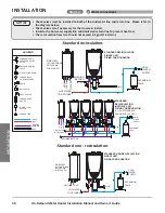
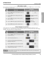
• If you connect more child units than allowed in the above table, surplus units will not operate
within the Easy Link System.
• The set temperature for the system can only be adjusted by the Parent heater.
• If the option remote is installed, it must be installed on the Parent heater. The remote will set the
temperature for all heaters.
• Only one remote can be connected to a water heater.
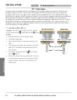
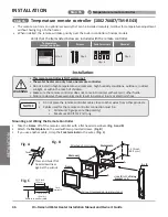
NOTICE
-Easy-Link connection procedures-
• The dark squares indicate the correct position of the DIP switch.
PA
RENT
Communication cable
Connectors
Middle bank of
DIP switches
1
1
1
2
2
2
PA
RENT
PA
RENT
PA
RENT
Connectors
Connectors
Connectors
1
2
3
4
5
6
OFF
ON
1
2
OFF
ON
1
2
3
4
5
6
OFF
ON
1
2
3
4
5
6
OFF
ON
1
2
3
4
5
6
Lower bank of
DIP switches
(540)
Middle bank of
DIP switches
(160X3P/180X3P
/199X3P)
Middle bank of
DIP switches
(199X3P)
Middle bank of
DIP switches
(199X3P)
or
Lower bank of
DIP switches
(540)
or
Lower bank of
DIP switches
(540)
or
PARENT UNIT
CHILD UNIT 1
CHILD UNIT 2
CHILD UNIT 3
(Only for 199X3P or 540)
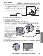
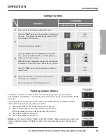
1. Make sure the power to the heaters are off.
2. If an optional remote controller is used, it must be connected to the
“PARENT”
unit. The remote will set the
temperature for the entire system. When the 160X3P/180X3P/199X3P model is the
“PARENT”
unit, the only
controller that can be used is the
100276687 (TM-RE43)
.
3. Select a 160X3P/180X3P/199X3P unit to be the
“PARENT”
unit. The
“PARENT”
unit should be one of the end
units.
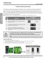
4. On the “PARENT” unit, locate the three banks of DIP switches at the near side of the computer board. Change
DIP switch No. 1 on the middle bank of DIP switches to the ON position. See the instructions of Change the DIP
switch as shown in the previous page. Do not change any DIP switches on any of the “CHILD” units.
5. Connect the “PARENT” connector of the “PARENT” unit to the “1” connector of the “CHILD-1” unit using the
supplied communication cable.
Steps 6 and 7 only apply to the 199X3P
6. Connect
“2”
connector of
“CHILD-1”
unit to the
“1”
connector of
“CHILD-2”
unit.
7. Connect
“2”
connector of
“CHILD-2”
unit to the
“1”
connector of
“CHILD-3”
unit.
8. Verify that all cables are connected as shown in the diagram above.
9. A: Turn on power to
“PARENT”
and wait for the (remote and/or built-in) controller to display
“1”
.
B. Turn on power to
“CHILD-1”
and wait for the (remote and/or built-in) controller to display the assigned #.
C: Turn on power to
“CHILD-2”
(If installed) and wait for the (remote and/or built-in) controller to display the
assigned #.
D: Turn on power to
“CHILD-3”
(If installed) and wait for the (remote and/or built-in) controller to display the
assigned #.
The numbering system automatically allocates the unit number to each
CHILD
water heater in the Easy-Link System,
in accordance with the table on p. 50.
INSTALLATION
Step 18:
Easy-Link System
Summary of Contents for 160X3P
Page 84: ...7J8071 1 2000570774 REV B...


