


INS
TALLA
TION
On-Demand Water Heater Installation Manual and Owner’s Guide
35
INSTALLATION
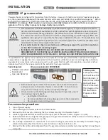
Step 11:
LP gas conversion
Check combustion status - measuring CO
2
value using a CO
2
gas meter
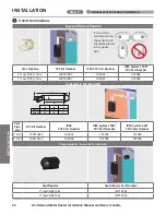
Tools Required: Phillips Screwdriver, T-15 Torx driver, CO
2
Gas meter
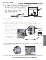
1. Ensure that the water heater is not in operation.
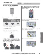
2. Locate the outlet venting port and remove the screw and the cover off the
outlet venting port. (Figure A)
3. Connect a CO
2
gas meter to the outlet venting port. (Figure A)
4. Turn on power supply to the water heater.
5. Turn on both gas and water valves to the water heater.
6. Check if the PCB is pulled out. (Figure B)
7. Turn on hot water fixtures to produce a flow to activate the water heater.
8. Verify the
Minimum combustion
as follows:
a. Press and hold the “MIN” button on the PCB. (See Figure B.)
b. Compare the reading on the CO
2
gas meter to the values in the table
below.* If it does not fall within the acceptable range, refer to the
following “Adjusting gas ratio at minimum combustion.”
*It may take some time for the CO
2
gas meter to become stable.
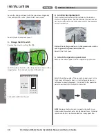
Adjusting gas ratio at minimum combustion
i. Locate the adjusting port on the gas valve. (See Figures A and C.)
ii. Remove the screw cover from the adjusting port with a T-15 Torx driver.
iii. Press and hold down the “MIN” button on the PCB. While holding
down the “MIN” button, turn the screw clockwise to increase or turn
the screw counterclockwise to decrease the CO
2
value and fall into the
range of CO
2
value in the table below with the driver. (See Figure C.)
iv. Verify the Maximum combustion to confirm proper combustion status
after adjusting as follows.
a. Turn on hot water fixtures to produce a high flow. If an isolation
valve is installed, hook up a water hose to the hot outlet and run
water at maximum rate.
b. Press and hold the “MAX” button on the PCB. (See Figure B.)
c. Compare the reading on the CO
2
gas meter to the values in the table
below.* If it does not fall within the acceptable range, refer to the above “Adjusting gas ratio at minimum
combustion.”
*It may take some time for the CO
2
gas meter to become stable.
9. After gas ratio has been adjusted, turn off the power supply and turn off both gas and water valves. Next, replace
the adjusting port screw securely. If the screw isn’t fastened securely at this time, it may cause a gas leak.
10. Remove the CO
2
gas meter from the outlet venting port and reinstall the removed cover on the outlet venting port
with the removed screw. (Go back to
the step 21
of
Gas conversion procedure
.)
Models for
Propane
160X3P
180X3P
199X3P
CO
2
value
%
Max.
10.2 ± 0.5
Max.
10.2 ± 0.5
Max.
10.2 ± 0.5
Min.
10.3 ± 0.5
Min.
10.3 ± 0.5
Min.
10.3 ± 0.5
BTU
Input
BTU/h
Max.
160,000
Max.
180,000
Max.
199,000
Min.
9,000
Min.
9,000
Min.
9,000
- CO
2
value -
Figure A
Outlet venting port
Adjusting port
MAX
MIN
Figure B
Figure C
Adjusting port
Summary of Contents for 160X3P
Page 84: ...7J8071 1 2000570774 REV B...


