background image

Venus 29xx Series SIP 

User‟s Manual 

xi 

Figure 3-59


QoS Configuration ............................................................................................................... 111


Figure 3-60


Port Based Vlan Configuration ............................................................................................ 112


Figure 3-61


Vlan Tag Configuration ....................................................................................................... 112


Figure 3-62


FM Monitoring .................................................................................................................... 114


Figure 3-63


FM Clear .............................................................................................................................. 115


Figure 3-64


Ethernet Performance .......................................................................................................... 116


Figure 3-65


Call Control Status ............................................................................................................... 116


Figure 3-66


RTP Status ............................................................................................................................ 117


Figure 3-67


SIP Agent Status................................................................................................................... 117


Figure 3-68


SIP Call Initiation Status ...................................................................................................... 118


Figure 3-69


Clear Performance Message ................................................................................................ 118


Figure 3-70


Ping ...................................................................................................................................... 119


Figure 3-71


result of ping a connected IP device .................................................................................... 119


Figure 3-72


result of ping a disconnected IP device ................................................................................ 119


Figure 3-73


Stun ...................................................................................................................................... 120


Figure 3-74


result of stun a disconnected Stun server ............................................................................. 120


Figure 3-75


Traceroute ............................................................................................................................ 120


Figure 3-76


Firmware Upgrade ............................................................................................................... 121


Figure 3-77


Step 1 of F/W Upgrading ..................................................................................................... 122


Figure 3-78


Step 2 of F/W Upgrading ..................................................................................................... 123


Figure 3-79


F/W Upgrading failure ......................................................................................................... 124


Figure 3-80


Step 3 of F/W Upgrading ..................................................................................................... 124


Figure 3-81


Step 4 of F/W Upgrading ..................................................................................................... 125


Figure 3-82


Config Up/Down.................................................................................................................. 125


Figure 3-83


Set Config uploading parameters ......................................................................................... 127


Figure 3-84


Config uploading ................................................................................................................. 127


Figure 3-85


Config uploading failure ...................................................................................................... 128


Figure 3-86


Set config downloading parameters ..................................................................................... 128


Figure 3-87


Config downloading ............................................................................................................ 129


Figure 3-88


Config downloading failure ................................................................................................. 129


Figure 3-89


Syslog Upload ...................................................................................................................... 130


Figure 3-90


Reset to Default ................................................................................................................... 131


Figure 3-91


Reset finished ....................................................................................................................... 131


Figure 3-92


Reset to Default ................................................................................................................... 132


Figure 3-93


Reboot finished .................................................................................................................... 132


Figure 3-94


System information Status ................................................................................................... 133


Figure 3-95


Ethernet Status ..................................................................................................................... 134


Figure 3-96


Analog Status ....................................................................................................................... 135


Figure 3-97


Routing Table Status ............................................................................................................ 135


Summary of Contents for VENUS 2916

Page 1: ...N 07008 00122 Headquarters No 25 Alley 15 Lane 120 Sec 1 Nei Hu Rd Taipei 114 Taiwan TEL 886 2 26583000 FAX 886 2 26583232 Beijing Branch Room 303 No 7 Gengfang International Building A13 Huayuan Road...

Page 2: ......

Page 3: ...ainet Communication System Corporation Other product names mentioned in this manual are used for identification purposes only and may be trademarks or trademarks of their respective companies The info...

Page 4: ...ll configure and operate TAINET s VENUS 29xx Series VoIP SIP Gateway The summary of this manual is as follows Chapter 1 Overview Chapter 2 Hardware Installation Chapter 3 Configuration and Management...

Page 5: ...are explained below Warning This symbol and associated text are used when death or injury to the user may result if operating instructions are not followed properly Note This symbol and associated tex...

Page 6: ...ive and shall provide satisfactory proof of such destruction to TAINET TAINET is not responsible for Products damaged by misuse neglect accident or improper installation or if repairs or modifications...

Page 7: ...e interruption of business or indirect special incidental or consequential damages of any kind TAINET shall do its best to provide end users with Software updates during the warranty period under this...

Page 8: ...Connection 18 2 2 3 Grounding 18 2 3 LED INDICATORS 20 2 4 CABLE CONNECTION 21 2 4 1 Connecting the Power Source 21 2 4 2 Connecting the IP Network via Ethernet 21 2 4 3 Connecting the Terminal 22 2 4...

Page 9: ...TATUS 133 3 7 1 System information 133 3 7 2 Ethernet 133 3 7 3 3Gmodem Info 134 3 7 4 Analog FXS FXO 135 3 7 5 Routing Table 135 3 7 6 ARP Table 135 3 8 FXS TO FXO LINE EXTENSION EXAMPLE 136 3 9 NAVI...

Page 10: ...Venus 29xx Series SIP User s Manual viii APPENDIX C CODE DETERMINATION FLOW CHART 209...

Page 11: ...08 8S Series Telephony Interface 22 Figure 2 2 VENUS 2908 4S4O Series Telephony Interface 22 Figure 2 3 Twisted Pair Cable 25 Figure 3 1 Connecting to the PC 28 Figure 3 2 The Login Page 29 Figure 3 3...

Page 12: ...Configuration 63 Figure 3 37 SNMP Configuration 65 Figure 3 38 TR069 Configuration 67 Figure 3 39 FM Configuration 68 Figure 3 40 Syslog Configuration 69 Figure 3 41 SIP General Configuration 71 Figur...

Page 13: ...Figure 3 75 Traceroute 120 Figure 3 76 Firmware Upgrade 121 Figure 3 77 Step 1 of F W Upgrading 122 Figure 3 78 Step 2 of F W Upgrading 123 Figure 3 79 F W Upgrading failure 124 Figure 3 80 Step 3 of...

Page 14: ...tus 136 Figure 3 99 CLI Main UI 145 Figure 3 100 Main CLI Tree 145 Figure 3 101 Status Commands 146 Figure 3 102 Prompt of Save command 147 Figure 3 103 Set command 147 Figure 3 104 Show command 149 F...

Page 15: ...Configuration Items 54 Table 3 13 Description of PSTN Lifeline Items 58 Table 3 14 The System Configuration Menu Items 59 Table 3 15 Description of System General Items 59 Table 3 16 Description of NT...

Page 16: ...DHCP Items 109 Table 3 49 Description of DHCP Server Assign Items 110 Table 3 50 Description of QoS Items 111 Table 3 51 Description of Vlan Items 112 Table 3 52 The Maintenance Menu Items 113 Table 3...

Page 17: ...network VENUS 29xx Series bridges the PSTN and IP network Depending on the installed firmware VENUS 29xx Series supports Session Initiation Protocol SIP Media Gateway Control Protocol MGCP and MEGACO...

Page 18: ...Transparent FAX service or T 38 FAX Relay Supplemental Class 5 features like Call Forwarding Caller ID Display Blocking Call Returning Speed Dial Call Waiting Call Transfer Voice Message Indication H...

Page 19: ...and Password from unauthorized users Provide three user accounts with three levels of access privilege Provides a flexible dialing principles as well as speed dial using hot key and hotline direct di...

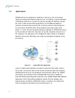
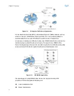
Page 20: ...lity voice service to the customers The deployment of an intelligent IP packet network for integrated data and voice service with billing accounting and management features can be soon built up Figure...

Page 21: ...the convenience of adding new Ethernet nodes new VENUS 29xx Series units can be installed easily to extend the amount of users To support more VENUS 29xx Series media gateway allows service providers...

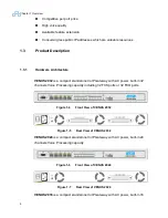
Page 22: ...one VoIP Gateway with AC power built in 32 channels Voice Processing capacity including 32 FXS ports or 32 FXO ports Figure 1 4 Front View of VENUS 2932 Figure 1 5 Rear View of VENUS 2932 VENUS 2924 i...

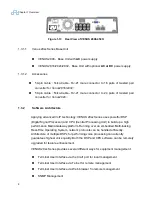
Page 23: ...eway with AC power built in 8 channels Voice Processing capacity and 1 PSTN port for dial line backup Figure 1 10 Front View of VENUS 2908 8S Figure 1 11 Rear View of VENUS 2908 8S VENUS 2908 4S4O is...

Page 24: ...ies uses powerful DSP Digital Signal Processor and CPU Central Processing Unit to build up a high performance Media Gateway platform Running over an embedded Multi tasking Real Time Operating System n...

Page 25: ...nt functions provided by TELNET are exactly the same as the craft port To maintain the consistency of configuration only one single user is allowed to login the terminal user interface via the craft p...

Page 26: ...3 2 4 SNMP Management The embedded SNMP agent in VENUS 29xx Series allows the device to be managed by the SNMP management system 1 3 2 5 TR 069 Management VENUS 29xx Series can be managed by the Auto...

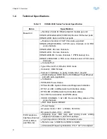
Page 27: ...onnector DB 9 Female Format 115 200bps no parity 8 data bits 1 stop bit WAN Interfaces IEEE 802 3u 10 100BaseT Fast Ethernet port with auto negotiation Indicators PWR LED Power Status SYS ALM LED Syst...

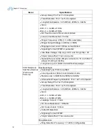
Page 28: ...fan out cable 50 pin connector to 16 or 24 RJ 11 plugs for wiring or testing Long haul up to 3 000m of 24 AWG lines design FXO Telephone Interface channel FXO 4 and FXO 32 Electronic Spec Signaling Ty...

Page 29: ...gress tones Dial tone Busy tone Ring back tone Congestion tone Off hook notice tone etc V 21 V 25 V 8 tone detection for automatic data fax voice switch over to G 711 voice coder Quality Enhancement T...

Page 30: ...eal Time G3 FAX over IP protocol supporting ITU T V 21 V 27ter V 29 and V 17 up to 14 400bps Management Console Telnet Web Browser proprietary authentication SNMP management TR069 management Remote Up...

Page 31: ...with Session Description Protocol SDP IETF RFC 3265 SIP Specific Event Notification IETF RFC 1889 RTP Real Time Protocol IETF RFC 2327 Session Description Protocol IETF RFC 2543 Session Initiation Pro...

Page 32: ...By Mechanism IETF RFC 3960 Early Media and Ringing Tone Generation in the SIP IETF RFC 3986 Uniform Resource Identifier Generic Syntax IETF RFC 4028 Session Time in the SIP IETF RFC 4566 Session Descr...

Page 33: ...the VENUS 29xx Series out of the container and place it securely on a flat clean surface Inspect the unit for signs of damage Immediately report any damage found Check the packing list against your o...

Page 34: ...2 2 3 Grounding The FCC requires telecommunications equipment to withstand electrical surges that may result from lightning strikes the VENUS 29xx Series device meet the requirements set forth by the...

Page 35: ...additional computer equipment you have connected to the device directly or through another device such as a terminal or printer should also be plugged into the same surge protector Make sure that the...

Page 36: ...CHANNEL LEDs Voice Channel Status Off On Hook State of the Telephone Handset Green Off Hook State of the Telephone Handset Eth0 Ethernet 0 Status Green Network Card is plug in and 10 100 Base T Link i...

Page 37: ...s are defined as following Table 2 2 10 100Base T Connection Pin Pin Function Pin Pin Function 1 TD 5 N C 2 TD 6 RD 3 RD 7 N C 4 N C 8 N C For connecting the 10 100Base T Fast Ethernet a Category 5 un...

Page 38: ...ation of the VENUS 29xx Series Speed and Data format 115 200bps none parity 8 data bits 1 stop bit and no flow control 2 4 4 Connecting the Telephony Devices VENUS 2908 supplies 8 2908 8S or 4 2908 4S...

Page 39: ...t 13 14 39 Port 14 15 40 Port 15 16 41 Port 16 17 25 Reserve 42 50 Reserve Venus 2924 2932 used the first RJ 21 interface with the pin configuration as shown in the table below Table 2 4 Venus2924 293...

Page 40: ...1 26 Port 17 2 27 Port 18 3 28 Port 19 4 29 Port 20 5 30 Port 21 6 31 Port 22 7 32 Port 23 8 33 Port 24 9 34 Port 25 10 35 Port 26 11 36 Port 27 12 37 Port 28 13 38 Port 29 14 39 Port 30 15 40 Port 31...

Page 41: ...5 6 31 Green Green and White Port 6 7 32 Blue Blue and White Port 7 8 33 Purple Purple and White Port 8 9 34 Gray Gray and Black Port 9 10 35 White Orange and Black Port 10 11 36 Pink Red and Black Po...

Page 42: ...Black White and Red Port 24 25 50 White and Blue White and Green Reserved 2 5 Hardware Diagnosis When the connections are all done turn on the power of the device to boot up the software VENUS 29xx S...

Page 43: ...eb browser to remotely control or maintain the device from anywhere in the global IP network 3 1 Quick Start Once when the VENUS 29xx Series is successfully started up please make sure that the connec...

Page 44: ...Mozilla Firefox Netscape Navigator etc to enter the web page 2 Terminal Emulation based By using the VT 100 ANSI compatible terminal emulation software such as Microsoft HyperTerminal user can config...

Page 45: ...ect to the gateway 3 1 1 3 Connect to VENUS 29xx Series 1 Web based The default parameters of VENUS 29xx Series Ethernet port are as follow Default IP address 192 168 0 1 Default gateway 192 168 0 254...

Page 46: ...ateway It will prompt the following messages Figure 3 3 The Login CLI Screen 3 1 1 4 Login Username and Password are required to login the VENUS 29xx for protection from unauthorized access to the dev...

Page 47: ...lays the Root Menu as shown in the following Figure Figure 3 5 The Root Screen 3 1 1 5 Command List Type the help in the Terminal Emulation when login successfully to show the Command List as shown in...

Page 48: ...save and run the setting The two commands have been executed as shown in the following Figure Figure 3 7 Set Ethernet Interface 3 1 1 7 Check the setting of Ethernet interface Type show interface Eth...

Page 49: ...PPOE use remote gateway enable PPPOE reconnect when link down enable MTU size 1500 MAC address admin The Ethernet interface has modified and then you can complete the Quick Start configuration in the...

Page 50: ...2 Network Connection Mode Configuration Items Description Necessary Network Connection Mode Default Static IP Y If you select Static IP you need to set the VENUS 29xx Series network connection manuall...

Page 51: ...server is the backup of the first one Table 3 3 Static IP Configuration Items Description Necessary IP address The local IP address of the VENUS 29xx Y Net mask The net mask of the local IP Y Default...

Page 52: ...configuration if they are combined in a same system Table 3 4 SIP Server Configuration Items Description Necessary Domain Name The domain name of the Proxy Server N Proxy address IP address or domain...

Page 53: ...IP signaling the default value is UDP Y The SIP Server configuration web page is shown in the following Figure Figure 3 11 SIP Server Configuration Click the Next button to continue Caution You may se...

Page 54: ...umber Port2 8 or port2 32 Default increment Y User authentication ID Port1 No default N User authentication ID Port2 8 or port2 32 Default Same N User authentication password Port1 No default N User a...

Page 55: ...assword when the Sip proxy and the register require authentication Click the OK button and you come to the last page of the Quick start which shows you Save and Run the web server configuration Succee...

Page 56: ...ck Start configuration of the VENUS 29xx Series You can click the status of the top menu and select the Analog FXS FXO of the left panel to check the result of this process If you see Register state o...

Page 57: ...o be using the same network segment as Venus 29xx Series and directly connect PC to the WAN port of Venus 29xx Series Enter the default IP address http 192 168 0 1 to access the Web user interface Def...

Page 58: ...tions to comply with field application Select Configuration Interface Configuration Ethernet to setup desired IP address Net mask and Default Gateway or select DHCP or PPPOE for Venus to automatically...

Page 59: ...SIP realm Select realm index to 0 and change realm valid to Enable Click OK to confirm and select Save Run to apply Figure 3 19 SIP Realm 3 2 5 Analog FXS FXO Setting Setup user number and authentica...

Page 60: ...iguration and Management 44 Figure 3 20 Analog FXS FXO settings 3 2 6 Status Check After all configurations are done user can check the current registration status at Status Analog FXS FXO Figure 3 21...

Page 61: ...Default Password Operating Administrator admin admin System manager Full control Operator user Only allow Ethernet configuration and monitor Monitor guest Only allow monitor 1 Web based After input t...

Page 62: ...tyle of the Web UI Indications point out the layout of the UI and help user to navigating through the User Interface There are three categories in the main menu Status Configuration and Maintenance Ea...

Page 63: ...tatus of 3G modem connection Analog FXS FXO Show the state of each FXS FXO Routing table Show the routing table ARP table Show the ARP table Configuration Quick Start A guide for user to start the sys...

Page 64: ...t SIP Call Initiation and Clear Notes NAT DHCP server are displayed if interface eth1 is in router mode Diagnostics Tools including Ping STUN Traceroute Device Control F M Upgrade Config Up Down Syslo...

Page 65: ...Region Profile DSP Allocation DDNS NAT Traversal SLIC Configuration and Meter Configuration Data Configuration Configure Static Routing NAT Mapping DHCP Sever QoS and VLAN Management Save Run Save all...

Page 66: ...GModem 3G Modem configuration PSTN Lifeline 2908 8S Model only PSTN configuration 3 5 2 1 Ethernet Configuration There are two Ethernet interfaces in VENUS 2908 and five Ethernet interfaces in VENUS 2...

Page 67: ...Chapter 3 Configuration and Management 51 Figure 3 27 Ethernet Configuration...

Page 68: ...PPoE server IP address Quick Start parameter The static IP address of specified interface Net mask Quick Start parameter The net mask of specified interface Default gateway Quick Start parameter The d...

Page 69: ...ay as VENUS 2908 default gateway PPPoE reconnect when link down 1 disable 2 enable default MTU size The MTU size of specified interface MAC address The MAC address of specified interface configurable...

Page 70: ...e means either FXS interface or FXO interface Generally the total number is different for each model The configuration parameter is specified by each interface Port Numbers 1 to 8 or 1 to 32 Figure 3...

Page 71: ...able default 3 Enable Realm Index Quick Start parameter The assigned realm index 0 7 Assume the realm 0 always exists Local service port number Quick Start parameter Local service port number Default...

Page 72: ...s used in the generated INVITE request The header also depends on the calling Privacy allowed or restricted The P asserted or P preferred headers are used to present the originating party s Caller ID...

Page 73: ...2 Description of 3G Modem Configuration Items Field Description Country Country of 3G modem network Telecom Telecom of 3G modem network 3G Network Network type to be used in 3G modem connection APN Ac...

Page 74: ...able 3 13 Description of PSTN Lifeline Items Field Description Prefix for PSTN line seizure Default 1 The function code to use PSTN Lifeline PSTN max ring off time 30 70 100ms base Default is 40 Lifel...

Page 75: ...elnet server Provision Configuration of the Provision SNMP Configuration of the Simple Network Management Protocol SNMP agent TR069 Configuration of CPE WAN Management Protocol CWMP or TR069 agent FM...

Page 76: ...the network By synchronizing time to a network time source traffic handling maintenance and debugging actions become simplified for the network administrator Figure 3 33 NTP Configuration Table 3 16 D...

Page 77: ...tion of NTP reboot hour in 24 hours format If the configuration is finished click OK button below the web page to confirm changes or click Cancel button to deny it 3 5 3 3 User Management Configuratio...

Page 78: ...elow the web page to confirm changes or click Cancel button to deny it 3 5 3 4 UI Management Configuration Venus 29xx Series has one build in Telnet server and one build in WEB server for remote manag...

Page 79: ...Ethernet interface 1 1 Disable 2 Enable Unsecured Default Web server port Web service port number of TCP Default is 80 Web Server Idle Timeout Sets the timeout for disconnection of an idle web session...

Page 80: ...is used for authentication Provisioning user password The password is used for authentication Provisioning file name The name of provisioning file Provisioning file encryption Default disable Enable...

Page 81: ...Chapter 3 Configuration and Management 65 3 5 3 6 SNMP Figure 3 37 SNMP Configuration...

Page 82: ...e System location The system location System contact The contact information Get community The get community and default is public Set community The set community and default is private Trap community...

Page 83: ...his is a component in the broadband network responsible for auto configuration of the CPE for advanced services CPE port The port of CPE Inform interval sec The inform time interval in seconds Auth mo...

Page 84: ...s Field Description CPU usage Threshold 0 100 If current CPU usage exceeds the threshold create an alarm message Default 100 DSP usage Threshold 0 100 If current DSP usage exceeds the threshold create...

Page 85: ...Figure 3 40 Syslog Configuration Table 3 23 Description of Syslog Items Field Description Log Mode 1 Disable Default 2 Remote Server 3 Local File System Log Server IP IP address of the Log Server Log...

Page 86: ...Chapter 3 Configuration and Management 70 3 5 4 SIP Configuration 3 5 4 1 SIP General Configuration...

Page 87: ...tion can be use to avoid packets from unknown address T1 time An estimate of the round trip time RTT for SIP protocol default value is set to 500 ms Password with md5 1 Disable Default 2 Enable Reg au...

Page 88: ...gnal through INFO message Subscription mode 1 Disable Default 2 Enable Register subscription Pound Symbol mode 1 Disable Default use 23 if need to report in URI 2 Enable use in Invite URI Ring mode Ri...

Page 89: ...Tel format number in the Register request Register Fail No Resend 1 Disable Default Prefer to resend the Register request when register fail 2 Enable Prefer to not resend the Register request when reg...

Page 90: ...finished click OK button bellow the web page to confirm changes or click Cancel button to deny it 3 5 4 2 SIP Realm Configuration User can use different realm to get different Registrar and Proxy par...

Page 91: ...rom the primary Proxy the gateway tries to communicate with the redundant Proxy Proxy port 5060 Default Quick Start parameter Primary proxy service port number Redundant Proxy address NULL Default IP...

Page 92: ...Port Quick Start parameter Outbound proxy service port number Transport way Quick Start parameter Transport protocol and valid options include AOR name If AOR name is specified REGISTER message will u...

Page 93: ...uration The analog line could be managed in hunting group and we assume the maximum group number is 8 and valid index is 0 to 7 The hunting group is a logical UA and may contain multiple physical anal...

Page 94: ...realm Local service port number 5060 Default Group authentication ID Quick Start parameter The authentication user ID Group authentication password Quick Start parameter The authentication user passwo...

Page 95: ...SIP URI host names per called number you need to configure the Phone Routing Table Figure 3 44 SIP Phone Routing Table Configuration Table 3 27 Description of SIP Phone Routing Table Configuration It...

Page 96: ...umber which the user just dialed and see if it matches the prefix number configured in this field For example if current Dst prefix has an entry of 888 then numbers such as 88811 888535 88823582 would...

Page 97: ...Prefix Suffix Prefix The number to be added in front of the dialed or final output number Suffix The number to be added at the end of the dialed or final output number For example if the final dialed...

Page 98: ...long An asterisk represents all numbers Strip Digit Number of digits to be removed from the left of the telephone number prefix or enter the number of digits in brackets to remove from the right of t...

Page 99: ...46 RTP Management Configuration Table 3 29 Description of RTP Management Configuration Items Field Description RTP base port 30000 Default The base port number and total 32 numbers are reserved for sp...

Page 100: ...me 30 Default Valid value is 30 and 60 in ms G726 default ptime 20 Default Valid value is 10 20 and 30 in ms G729 default ptime 20 Default Valid value is 10 20 30 40 50 and 60 in ms Use RFC2833 RFC283...

Page 101: ...elay Playout minimum delay ms Playout nominal delay Playout nominal delay ms Playout max delay Playout maximum delay ms Pob starve timeout Pob starve timeout ms Adaptive playout Adaptive playout If th...

Page 102: ...Chapter 3 Configuration and Management 86 Figure 3 47 Calling Feature Configuration Table 3 30 Description of Calling Feature Configuration Items...

Page 103: ...ce 0 not limit E164 mode Disable Default Enable E164 function Dialing prefix To append the prefix to the dial string Used for all the users of the device to share a dialing prefix Emergency call numbe...

Page 104: ...rent call if Call Waiting is enable After the user On Hook the function reconverts Call ID block temp active code Default 67 To block call ID for current call ever the user Call ID block enable or dis...

Page 105: ...er that User B stop ring and conversion A and C Fax Signaling Method Determines the SIP signaling method used to establish and convey a fax session after a fax is detected 1 No fax negotiation using S...

Page 106: ...Modem tone detection and send reInvite to build modem communication 1 Disable Default 2 Callee 3 Caller 4 Both callee caller Report Flash 1 Disable Default 2 Enable Report the flash hook event by re i...

Page 107: ...lick Cancel button to deny it Table 3 31 Call Waiting Operation Call Waiting Call Hold Three way conference mode Call Waiting Operation Disable Not support Enable Disable Not support Enable Enable Dis...

Page 108: ...Chapter 3 Configuration and Management 92 Conversion A and B C dial A A Flash Hook Do three way conference A Flash Hook A Bye C Conversion A and B...

Page 109: ...00 Send Refer To B To C B Call ConvServ C Call ConvServ B and C Send Notify with terminal to A A Bye B A Bye C A B C and ConvServ in a conference A B C and ConvServ in a conference A Hook On A Bye Con...

Page 110: ...onversion A and C A Flash Hook dial 1 A hold C Conversion A and B A hold C Conversion A and B A Flash Hook dial 2 A hold B Conversion A and C Conversion A and B C dial A A Flash Hook dial 3 Do three w...

Page 111: ...dials A A and B converse A hold B A call C A and C converse A B C converse A and B converse C call A A and C converse A B C converse 0 Bye C Terminate C Bye C Bye C 1 Bye B Bye B Bye B Bye B 2 A and B...

Page 112: ...onversion A and B A Hold B A dial Unattended Call Transfer function code 66 A play Stutter Tone A dial C number A play Busy Tone and A Hook On C Ring C Hook Off Conversion C and B 3 5 5 3 Region Profi...

Page 113: ...DEN 7 MALAYSIA 8 FRENCH 9 CZECH 10 SLOVAKIA 11 AUSTRALIA 12 POLAND 13 BULGARIA 14 NEWZEALAND Region code The Country Region code Area code The area code International long distance access code The int...

Page 114: ...requency 25 Default Ring frequency and different with different region ID valid value is 17 to 50 Default Ring Ring 0 Ring 7 Ring Splash Ring cadence On 1 in 100ms Note index 1 8 means distinctive rin...

Page 115: ...ield Description Tone ID 0 17 1 6 Tone frequency 1 First index means tone id and second index means tone element 0 busy 1 ring_back 2 congestion 3 dial_tone 4 dial_tone2 5 out_of_service 6 addr_ack 7...

Page 116: ...on 0 17 1 6 Tone element duration If the configuration is finished click OK button bellow the web page to confirm changes or click Cancel button to deny it 3 5 5 4 DDNS Dynamic DNS DDNS is a method pr...

Page 117: ...tication If the configuration is finished click OK button below the web page to confirm changes or click Cancel button to deny it 3 5 5 5 NAT Traversal Configuration User may assign one NAT address if...

Page 118: ...erver Disable this function to assign IP address of 0 0 0 0 STUN server address Stun server IP address or domain name STUN server port 0 Default Stun server service port number STUN polling interval 6...

Page 119: ...ue If the configuration is finished click OK button below the web page to confirm changes or click Cancel button to deny it 3 5 5 7 Meter Configuration Meter Configuration is used to adjust the settin...

Page 120: ...n Static Routing Eth1 under Router mode Configuration static routing information which use for LAN NAT mapping Eth1 under Router mode Configuration NAT information which use for LAN DHCP Server Eth1 u...

Page 121: ...Chapter 3 Configuration and Management 105 Figure 3 55 Static Routing Configuration...

Page 122: ...g data to next hop 3 5 6 2 NAT mapping In computer networking network address translation NAT is the process of modifying network address information in datagram packet headers while in transit across...

Page 123: ...t of wan which is used for access through internet Protocol The NAT mapping protocol Default disable TCP mapping TCP protocol only UDP mapping UDP protocol only If the configuration is finished click...

Page 124: ...Chapter 3 Configuration and Management 108 Figure 3 57 DHCP Server Configuration...

Page 125: ...he DHCP server domain name DNS server IP address 1 4 The DNS server IP address use for LAN you can configure four DNS server Default gateway IP address 1 4 The default gateway IP address for LAN you c...

Page 126: ...to a static IP Host name The host name of the static IP MAC address The MAC address of the static IP 3 5 6 4 QoS Configuration DiffServ is architecture providing different types or levels of service...

Page 127: ...DSCP The signaling DSCP Default is 37 Voice DSCP The voice DSCP Default is 37 Signaling TOS The signaling TOS Default is 6 Voice TOS The voice TOS Default is 6 If the configuration is finished click O...

Page 128: ...lan Tag Configuration Table 3 51 Description of Vlan Items Field Description VLAN Group 6 Eth0 Eth1 Eth2 4 local Default no select VLAN Tag 5 Eth0 Eth1or Eth2 4 1 no 2 yes VLAN Priority 6 Default 0 No...

Page 129: ...FM Records Performance Management Ethernet Call Control RTP SIP Agent SIP Call Initiation NAT DHCP Server and Clear PM Records Diagnostics Do Ping STUN test and Traceroute Device Control F M Upgrade...

Page 130: ...guration and Management 114 Figure 3 62 FM Monitoring Table 3 54 Description of FM Monitoring Field Description Refresh Interval 1 disable 2 10 s Default 3 20 s 4 30 s 5 40 s 6 50 s 7 60 s Refresh the...

Page 131: ...ear 3 6 2 Performance Management Table 3 55 The Performance Management Menu Items Menu Description Ethernet Ethernet status Call Control Call Control status RTP RTP status SIP Agent SIP Agent status S...

Page 132: ...Chapter 3 Configuration and Management 116 3 6 2 1 Ethernet Figure 3 64 Ethernet Performance 3 6 2 2 Call Control Figure 3 65 Call Control Status...

Page 133: ...Chapter 3 Configuration and Management 117 3 6 2 3 RTP Figure 3 66 RTP Status 3 6 2 4 SIP Agent Figure 3 67 SIP Agent Status...

Page 134: ...6 2 6 Clear Figure 3 69 Clear Performance Message 3 6 3 Diagnostics Table 3 56 The Fault Management Menu Items Menu Description Ping Ping the specify IP device Stun Check a Simple Traversal of User Da...

Page 135: ...node For example to check whether the Proxy Server is reachable or is alive Make sure you configure the correct subnet mask and the IP address of the default gateway Figure 3 70 Ping Click OK button...

Page 136: ...llow the web page to do or click Cancel button to deny it Figure 3 74 result of stun a disconnected Stun server 3 6 3 3 Traceroute Figure 3 75 Traceroute Click OK button below the web page to do or cl...

Page 137: ...n binary code format can be remotely downloaded from a TFTP server and written into the internal flash memory of the VENUS 2908 Series Check with our technical support for the availability of the late...

Page 138: ...e transport protocol User Password User password of the server Binary file name This item tells VENUS 29xx Series that file should be loaded from TFTP server The firmware must be in the binary format...

Page 139: ...Download Figure 3 78 Step 2 of F W Upgrading The download process will take about 20 seconds If the TFTP server is not running or firmware file does not exist the upgrading will abort Caution Upgrade...

Page 140: ...3 of F W Upgrading Caution Do not write the software with incorrect checksum and do not reset the device while performing flash write In case the flash write is abnormally disrupted VENUS Series can s...

Page 141: ...d Step 4 Reboot system Figure 3 81 Step 4 of F W Upgrading After upgrade the firmware the device will reboot and execute the new firmware 3 6 4 2 Config Up Down Get or set the whole device configurati...

Page 142: ...r Address Default is 0 0 0 0 Server port Default TFTP Server port is 69 User name User name of server User Password User password of server Configuration file name The configuration File name to be Up...

Page 143: ...utton below the web page to execute uploading or click Cancel button to give up The whole process will take about 5 seconds Step 2 Uploading Figure 3 84 Config uploading If the uploading has succeeded...

Page 144: ...failure B Download Step 1 Set downloading parameters Figure 3 86 Set config downloading parameters If the configuration is finished click OK button below the web page to execute Upload Download or cli...

Page 145: ...ll be changed to as the config file named test ini in you TFTP server root directory If the TFTP server is not running or config file does not exist the downloading will abort Figure 3 88 Config downl...

Page 146: ...is 0 0 0 0 Server port Default TFTP Server port is 69 Syslog file name The system log File name to be Uploaded 3 6 4 4 Reset to Default This feature is used to reset all the settings to the factory d...

Page 147: ...up After click the Reset button the device will reboot with the default configuration Figure 3 91 Reset finished 3 6 4 5 Reboot After changing some configurations of the device it may be required to r...

Page 148: ...Restart button below the web page to reboot or click Cancel button to give up After click the Restart button the device will reboot Figure 3 93 Reboot finished Caution Reset the gateway only when ther...

Page 149: ...come to System info page This Page will display the basic system information of the VENUS 29xx as in the following figure Figure 3 94 System information Status 3 7 2 Ethernet Click the Ethernet of the...

Page 150: ...Configuration and Management 134 Figure 3 95 Ethernet Status 3 7 3 3Gmodem Info 3Gmodem Info shows the current status of 3G modem connection user can also select to connect or disconnect 3G modem con...

Page 151: ...e Figure 3 96 Analog Status 3 7 5 Routing Table Click the Routing Table of the top menu come to Routing Table page This Page will display Routing Table information of the Proxy Server in the following...

Page 152: ...Table 3 61 Description of Routing Table Monitoring Items Field Description IP Address Proxy Server IP Address HW Address Proxy Serve MAC Address Iface Interface Eth0 Eth1 or Eth2 4 3 8 FXS to FXO line...

Page 153: ...Chapter 3 Configuration and Management 137 2 Venus 2932 FXS Configuration SIP Configuration General...

Page 154: ...uration Analog FXS FXO Configure hotline as 2001 for Port 1 1001 since this FXS port will dial out to remote FXO directly Configure hotline as 2002 for Port 2 1002 since this FXS port will dial out to...

Page 155: ...Chapter 3 Configuration and Management 139 5 Venus 2932 FXS Configuration Save Run 6 Venus 2932 FXS Configuration SIP Configuration General INFO mode info...

Page 156: ...Chapter 3 Configuration and Management 140 7 Venus 2932 FXO Configuration Quick Start Static IP...

Page 157: ...Chapter 3 Configuration and Management 141 8 Venus 2932 FXO Configuration SIP Configuration General 9 Venus 2932 FXO Configuration SIP Configuration Phone Routing Table...

Page 158: ...Chapter 3 Configuration and Management 142 10 Venus 2932 FXO Configuration Save Run 11 Venus 2932 FXO Configuration Advanced Configuration Calling Feature Report Flash By info plain text...

Page 159: ...Configuration Analog FXS FXO Configure hotline as 1001 for Port 1 2001 since this FXO port will dial out to remote FXS directly Configure hotline as 1002 for Port 2 2002 since this FXO port will dial...

Page 160: ...r better compatibility When setup complete when user on FXS port off hooks it will be directly routed to remote FXO port When FXO port is being called from PSTN or PBX side the call will be directed t...

Page 161: ...Displays Command Help Table Status Commands st Displays System Status Information Configuration Commands save Save System Configuration set Set System Configuration show Show System Configuration Mai...

Page 162: ...46 3 9 1 Syntax The command line syntax is command parameter The following are some example commands set tcid 3 rxgain 5 venus card 4 fxs ring_freq 20 3 9 2 Status Commands Display the system status i...

Page 163: ...tion st analog Analog information st rt Route table information st arp ARP table information 3 9 3 Configuration Commands 3 9 3 1 Save Save the parameters have been changed to system Figure 3 102 Prom...

Page 164: ...n options set system snmp options set system tr069 options set system threshold options Set sip options admin set sip set sip general options set sip realm options set sip group options set sip phone_...

Page 165: ...mmand set advance tiu options Set data options admin set data set data dhcp options set data nat_mapping options set data static_route options set data qos options set data vlan options 3 9 3 3 Show S...

Page 166: ...tion show system security Display security settings information show system provision Display provision settings information show system snmp Display SNMP settings information show system tr069 Displa...

Page 167: ...isplay advanced region settings information show advance nat_traversal Display advanced NAT traversal settings information show advance ddns Display advanced DDNS settings information show advance dsp...

Page 168: ...statistic information mt pm agent Show the sip statistic information mt pm ci Show the call initial statistic information mt pm nat Show the NAT statistic information mt pm dhcps Show the DHCP Server...

Page 169: ...ilt Inter line test mt dia da Dsp alloction mt dc mt dc upgrade Firmware upgrade mt dc download Configure file download mt dc upload Configure file upload mt dc restore Configuration information Rest...

Page 170: ...Chapter 3 Configuration and Management 154 Figure 3 106 Spy command...

Page 171: ...evel superfluous information 1 Function Enter Level entering function 2 Event Level normal and expected event i e link up 3 Default Minor Error Level minor unexpected event 4 Major Error Level major u...

Page 172: ......

Page 173: ...ion file to TFTP server through menu tree Please refer to Section 3 5 3 2 for information on configuration upload and download 4 1 File Format The configuration file must be in ASCII text format use t...

Page 174: ...0 0 0 0 dhcp_iad_0 0 dhcp_dns_0 0 dhcp_server_addr1_0 0 0 0 0 dhcp_net_mask1_0 0 0 0 0 dhcp_server_addr2_0 0 0 0 0 dhcp_net_mask2_0 0 0 0 0 pppoe_user_name_0 user pppoe_user_pwd_0 123 pppoe_dns_0 0 pp...

Page 175: ..._mask1_1 0 0 0 0 dhcp_server_addr2_1 0 0 0 0 dhcp_net_mask2_1 0 0 0 0 pppoe_user_name_1 pppoe_user_pwd_1 pppoe_dns_1 0 pppoe_gateway_1 1 pppoe_reconnect_1 1 mtu_size_1 1500 interface_pstn seizure_pref...

Page 176: ...max_flash_time_0 500 line_reversal_0 1 caller_id_mode_0 0 hotline_number_0 hotline_timeout_0 0 realm_index_0 0 local_port_0 5060 user_auth_id_0 user_auth_pwd_0 digitmap_0 x always_number_0 busy_number...

Page 177: ...0 fxs_answ_clear_detect_0 300 fxs_cpc_wait_0 200 fxs_cpc_dur_0 850 fxs_ring_id_0 255 fxs_cid_type_0 1 fxs_local_batt_conn_rev_0 1 fxs_rem_batt_conn_rev_0 1 fxs_batt_ring_rev_0 0 answer_wait_0 65535 ca...

Page 178: ...1 2 min_flash_time_1 50 max_flash_time_1 500 line_reversal_1 1 caller_id_mode_1 0 hotline_number_1 hotline_timeout_1 0 realm_index_1 0 local_port_1 5060 user_auth_id_1 user_auth_pwd_1 digitmap_1 x alw...

Page 179: ...ect_1 150 fxs_orig_clear_detect_1 300 fxs_answ_clear_detect_1 300 fxs_cpc_wait_1 200 fxs_cpc_dur_1 850 fxs_ring_id_1 255 fxs_cid_type_1 1 fxs_local_batt_conn_rev_1 1 fxs_rem_batt_conn_rev_1 1 fxs_batt...

Page 180: ..._2 1002 user_name_2 register_mode_2 2 min_flash_time_2 50 max_flash_time_2 500 line_reversal_2 1 caller_id_mode_2 0 hotline_number_2 hotline_timeout_2 0 realm_index_2 0 local_port_2 5060 user_auth_id_...

Page 181: ...20 fxs_onhook_db_2 20 fxs_seize_detect_2 150 fxs_orig_clear_detect_2 300 fxs_answ_clear_detect_2 300 fxs_cpc_wait_2 200 fxs_cpc_dur_2 850 fxs_ring_id_2 255 fxs_cid_type_2 1 fxs_local_batt_conn_rev_2...

Page 182: ...dr_len_2 0 plar_addr_digits_2 user_number_3 1003 user_name_3 register_mode_3 2 min_flash_time_3 50 max_flash_time_3 500 line_reversal_3 1 caller_id_mode_3 0 hotline_number_3 hotline_timeout_3 0 realm_...

Page 183: ...ec_config_3 1 fxs_offhook_db_3 20 fxs_onhook_db_3 20 fxs_seize_detect_3 150 fxs_orig_clear_detect_3 300 fxs_answ_clear_detect_3 300 fxs_cpc_wait_3 200 fxs_cpc_dur_3 850 fxs_ring_id_3 255 fxs_cid_type...

Page 184: ...0 pause_duration_3 1000 plar_addr_len_3 0 plar_addr_digits_3 user_number_4 1004 user_name_4 register_mode_4 2 min_flash_time_4 50 max_flash_time_4 500 line_reversal_4 1 caller_id_mode_4 0 hotline_numb...

Page 185: ...2 pref_fax_coding_4 1 companding_4 4 ec_config_4 1 fxs_offhook_db_4 20 fxs_onhook_db_4 20 fxs_seize_detect_4 150 fxs_orig_clear_detect_4 300 fxs_answ_clear_detect_4 300 fxs_cpc_wait_4 200 fxs_cpc_dur...

Page 186: ..._off_time_4 200 tone_out_power_4 130 pause_duration_4 1000 plar_addr_len_4 0 plar_addr_digits_4 user_number_5 1005 user_name_5 register_mode_5 2 min_flash_time_5 50 max_flash_time_5 500 line_reversal_...

Page 187: ...gain_5 0 proto_5 6 last_set_state_5 2 pref_fax_coding_5 1 companding_5 4 ec_config_5 1 fxs_offhook_db_5 20 fxs_onhook_db_5 20 fxs_seize_detect_5 150 fxs_orig_clear_detect_5 300 fxs_answ_clear_detect_5...

Page 188: ...0 tone_out_on_time_5 200 tone_out_off_time_5 200 tone_out_power_5 130 pause_duration_5 1000 plar_addr_len_5 0 plar_addr_digits_5 user_number_6 1006 user_name_6 register_mode_6 2 min_flash_time_6 50 m...

Page 189: ...k_6 0 prefer_call_id_6 rx_gain_6 0 tx_gain_6 0 proto_6 6 last_set_state_6 2 pref_fax_coding_6 1 companding_6 4 ec_config_6 1 fxs_offhook_db_6 20 fxs_onhook_db_6 20 fxs_seize_detect_6 150 fxs_orig_clea...

Page 190: ...p_wait_6 65535 out_wait_6 400 out_type_6 0 tone_out_on_time_6 200 tone_out_off_time_6 200 tone_out_power_6 130 pause_duration_6 1000 plar_addr_len_6 0 plar_addr_digits_6 user_number_7 1007 user_name_7...

Page 191: ...er_number_7 wait_times_7 3 call_id_block_7 0 prefer_call_id_7 rx_gain_7 0 tx_gain_7 0 proto_7 6 last_set_state_7 2 pref_fax_coding_7 1 companding_7 4 ec_config_7 1 fxs_offhook_db_7 20 fxs_onhook_db_7...

Page 192: ...535 call_limit_7 65535 fax_holdover_7 2000 hangup_wait_7 65535 out_wait_7 400 out_type_7 0 tone_out_on_time_7 200 tone_out_off_time_7 200 tone_out_power_7 130 pause_duration_7 1000 plar_addr_len_7 0 p...

Page 193: ...in_name admin admin_pswd 21232f297a57a5a743894a0e4a801fc3 operator_name user operator_pswd d41d8cd98f00b204e9800998ecf8427e monitor_name guest monitor_pswd d41d8cd98f00b204e9800998ecf8427e use_radius_...

Page 194: ...ystem_provision prov_server_addr prov_server_port 69 prov_protocal 0 prov_user_name prov_user_pswd prov_file_name file_encryption 0 prov_timeout 0 system_snmp snmp_server_mode 0 snmp_server_port 161 s...

Page 195: ...terval 60 trap_dest_addr1 trap_dest_addr2 trap_dest_addr3 trap_dest_addr4 system_tr069 acsurl cpeport mode sip_general fqdn_mode 0 fqdn_name dns_query_type 0 trust_proxy 0 t1_time 500 regst_auth 0 pwd...

Page 196: ..._symbol_mode 0 ring_mode 0 discon_on_broken 0 broken_conn_timeout 60 current_disconnect 0 fallback_rout_table 0 prefer_rout_table 0 critical_digit_timer 4 partial_digit_timer 16 sip_realm realm_valid_...

Page 197: ..._port_0 5060 transport_way_0 0 aor_name_0 keep_alive_mode_0 0 keep_alive_interval_0 60 realm_valid_1 0 domain_name_1 proxy_addr_1 proxy_port_1 5060 redu_proxy_addr_1 redu_proxy_port_1 0 registrar_addr...

Page 198: ..._name_2 proxy_addr_2 proxy_port_2 5060 redu_proxy_addr_2 redu_proxy_port_2 0 registrar_addr_2 registrar_port_2 5060 backup_reg_addr_2 backup_reg_port_2 0 registration_time_2 3600 reregist_timing_2 100...

Page 199: ...egistrar_port_3 5060 backup_reg_addr_3 backup_reg_port_3 0 registration_time_3 3600 reregist_timing_3 100 outbd_proxy_addr_3 outbd_proxy_port_3 5060 transport_way_3 0 aor_name_3 keep_alive_mode_3 0 ke...

Page 200: ...roxy_addr_4 outbd_proxy_port_4 5060 transport_way_4 0 aor_name_4 keep_alive_mode_4 0 keep_alive_interval_4 60 realm_valid_5 0 domain_name_5 proxy_addr_5 proxy_port_5 5060 redu_proxy_addr_5 redu_proxy_...

Page 201: ...alm_valid_6 0 domain_name_6 proxy_addr_6 proxy_port_6 5060 redu_proxy_addr_6 redu_proxy_port_6 0 registrar_addr_6 registrar_port_6 5060 backup_reg_addr_6 backup_reg_port_6 0 registration_time_6 3600 r...

Page 202: ...0 registrar_addr_7 registrar_port_7 5060 backup_reg_addr_7 backup_reg_port_7 0 registration_time_7 3600 reregist_timing_7 100 outbd_proxy_addr_7 outbd_proxy_port_7 5060 transport_way_7 0 aor_name_7 ke...

Page 203: ...11 group_name_1 register_mode_1 0 realm_index_1 0 local_port_1 5060 group_auth_id_1 group_auth_pwd_1 involved_tcids_1 0 group_number_2 12 group_name_2 register_mode_2 0 realm_index_2 0 local_port_2 5...

Page 204: ...nvolved_tcids_3 0 group_number_4 14 group_name_4 register_mode_4 0 realm_index_4 0 local_port_4 5060 group_auth_id_4 group_auth_pwd_4 involved_tcids_4 0 group_number_5 15 group_name_5 register_mode_5...

Page 205: ...group_auth_id_6 group_auth_pwd_6 involved_tcids_6 0 group_number_7 17 group_name_7 register_mode_7 0 realm_index_7 0 local_port_7 5060 group_auth_id_7 group_auth_pwd_7 involved_tcids_7 0 sip_phonerout...

Page 206: ...o_codec 0 g711_ptime 20 g723_ptime 30 g726_ptime 20 g729_ptime 30 use_rfc2833 0 rfc2833_ptype 101 use_g726_codec 0 g726_16_ptype 2 g726_24_ptype 2 g726_32_ptype 2 g726_40_ptype 2 vad_mode 0 echo_cance...

Page 207: ...ling 0 max_call 0 e164_mode 0 dialing_prefix emerg_call_num1 emerg_call_num2 emerg_call_num3 emerg_call_num4 emerg_call_mode 0 call_hold 0 call_hold_mode 0 call_waiting 0 three_way_mode 0 confer_serve...

Page 208: ...l_method 1 t30_fax_codec 0 fax_tone_detection 0 modem_method 1 modem_codec 0 modem_tone_detect 0 advanced_region region_id 2 region_code area_code international_code domestic_code ring_frequency 25 ri...

Page 209: ..._0 40000 tone_numrow_0 2 tone_0_0 1 450 100 0 0 0 0 0 0 350 tone_0_1 0 0 0 0 0 0 0 0 0 350 tone_timeout_1 180000 tone_numrow_1 2 tone_1_0 1 450 100 0 0 0 0 0 0 1000 tone_1_1 0 0 0 0 0 0 0 0 0 4000 ton...

Page 210: ...0 0 0 0 125 tone_6_1 0 0 0 0 0 0 0 0 0 125 tone_6_2 1 600 240 0 0 0 0 0 0 125 tone_6_3 0 0 0 0 0 0 0 0 0 1 tone_timeout_7 1 tone_numrow_7 4 tone_7_0 1 450 200 0 0 0 0 0 0 250 tone_7_1 0 0 0 0 0 0 0 0...

Page 211: ...ne_12_1 0 0 0 0 0 0 0 0 0 100 tone_12_2 2 2130 150 2750 150 0 0 0 0 85 tone_12_3 0 0 0 0 0 0 0 0 0 5000 tone_timeout_13 30000 tone_numrow_13 2 tone_13_0 1 450 100 0 0 0 0 0 0 350 tone_13_1 0 0 0 0 0 0...

Page 212: ..._1 0 0 0 0 0 0 0 0 0 250 tone_17_2 1 400 130 0 0 0 0 0 0 250 tone_17_3 0 0 0 0 0 0 0 0 0 3250 advanced_nat nat_ip_addr 0 0 0 0 stun_server_addr stun_server_port 0 polling_interval 64 advanced_ddns ddn...

Page 213: ..._mode 1 protocol_mode_0 0 internal_ip_addr_0 0 0 0 0 inter_serv_port_0 0 exter_serv_port_0 0 data_dhcp dhcp_mode 0 dhcp_net_addr 0 0 0 0 dhcp_net_mask 0 0 0 0 domain_name dns_ip_addr0 0 0 0 0 dns_ip_a...

Page 214: ...ip_low4 0 0 0 0 free_ip_low5 0 0 0 0 free_ip_high1 0 0 0 0 free_ip_high2 0 0 0 0 free_ip_high3 0 0 0 0 free_ip_high4 0 0 0 0 free_ip_high5 0 0 0 0 assign_host_name_0 assign_ip_addr_0 0 0 0 0 assign_ma...

Page 215: ...t_vlan_id 0 data_vlan_id 0 signal_vlan_prior 0 voice_vlan_prior 0 mgt_vlan_prior 0 data_vlan_prior 0 vlan_tag_0 0 vlan_tag_1 0 vlan_vid_0 0 vlan_vid_1 0 vlan_vid_2 0 vlan_priority_0 0 vlan_priority_1...

Page 216: ...Chapter 4 Edit Configuration File 200 ram_threshold 100 dsp_threshold 100 end of configuration file...

Page 217: ...ate the problem 1 Cable Connections Make sure all the cables are connected correctly and firmly Check if you provide a correct power source 2 The Power Source The LED indicators offer some helpful inf...

Page 218: ...uter a cross cable instead of a straight cable may be used 5 IP Address Configuration Check if the IP address was assigned statically or obtained dynamically from a DHCP server If the DHCP client mode...

Page 219: ...a Local Call If the dial tone can be heard try to dial a local number to another port on the same gateway See it the ring back tone is heard and the called party are ringing See if the Channel LED fl...

Page 220: ...d network configuration in advance is very important Type of the Voice Codec selected is a big factor and tradeoff to the voice quality The PCM type codec G 711 u law or A law provide excellent voice...

Page 221: ...ll be forwarded to the specified user through the response 302 Call Forward Busy CFB Forward all the incoming calls while the local phone is busy All installed users can assign a busy call forward num...

Page 222: ...he current conversation partner Pressing another flash hook will hold the 3rd party 3 Way conference This feature allows user to make two call calls and mixed the RTP stream and make a 3 party joined...

Page 223: ...ed Access Device IADMS IAD Management Server ICMP Internet Control Message Protocol IETF Internet Engineering Task Force ITU T International Telecommunication Union Telecommunication MDU Multi Dwellin...

Page 224: ...Management Protocol TCP Transmission Control Protocol TELNET Telecommunication Network Protocol TFTP Trivial File Transfer Protocol UA User Agent UI User Interface UDP User Datagram Protocol URL Unif...

Page 225: ...nebook or extension number Does it match the number of internal phone book Is FXO auto_route enabled End No No No No Yes You will be connected with the destination number via VoIP gateway Does this sy...

Reviews: