background image

3060386 |  Geniox Air Handling Unit - User Manual

Roof curb master tables    |        5-2

Summary of Contents for Geniox 10

Page 1: ...Geniox Air handling unit User Manual EN Version 1 2 Document in original language Part number of this manual 3060386...

Page 2: ...Geniox Air Handling Unit User Manual 3060386...

Page 3: ...Information about the residual risks J Instructions on the protective measures during repair and maintenance Machine stability K The conditions of stability during use transportation assembly dismant...

Page 4: ...e for lifting 11 G 1 4 Pre assembly storage 12 G 2 Installation mechanical 12 G 2 1 Service Area in front of the unit 12 G 2 2 Supporting surface 12 G 2 3 Outdoor units support under the base frame of...

Page 5: ...the doors by using the key 35 M 3 Recommended maintenance intervals 36 M 4 Filters always replace filters with new filters with the same characteristics 36 M 4 1 Bag filters 38 M 4 2 Panel filters 40...

Page 6: ...Geniox Air Handling Unit User Manual 3060386...

Page 7: ...acked for shipping This means that the packaged product with normal handling will withstand the load conditions encountered in normal transit and in handling Your air handling unit should be inspected...

Page 8: ...is less Systemair s sole responsibility under this parts warranty will be to replace any part which fails to comply with this warranty during such warranty period provided customer has promptly report...

Page 9: ...t Pre heater 2 Hot Water Coil Pre heater 7 Energy Recovery 0 No Energy Recovery NE 1 Sensible Rotational Wheel RS 2 Enthalpy Rotational Wheel RE 3 Sensible Plate Heat Exchanger PS 4 Enthalpy Membrane...

Page 10: ...right hand unit is shown because the inspection doors are mounted on the right hand side of the unit when looked in direction of SUPPLY airflow The unit below is with energy recovery wheel Position D...

Page 11: ...FLA A A A Max Inlet Water Temp 200 F 93 C Max Outlet Air Temp 165 F 74 C Ref Design Pressures Low High 236 600 psig Ref R410A Max External Static Pressure in wc Pa in wc Pa Min Working Space Clearanc...

Page 12: ...ing GenioxG Panel filter GenioxF Bag filter GenioxC Energy recovery wheel GenioxQ Plate heat exchanger cross flow GenioxH Heating coil GenioxK Cooling coil GenioxE Plug fan GenioxD Silencer 6 General...

Page 13: ...ER DANGER DANGER RISK OF ELECTRIC SHOCK can cause injury or death Disconnect all remote electric power supplies before servicing RISQUE DE CHOCS LECTRIQUES peut causer des blessures et m me entra ner...

Page 14: ...R EAR PROTECTION BRUIT FORT PORTER UNE PROTECTION AUDITIVE ATTENTION CAUTION ROTATING BELT DRIVE KEEP HANDS CLEAR OF THE MACHINERY ENTRA NEMENT PAR COURROIE ROTATIVE GARDER LES MAINS HORS DE LA MACHIN...

Page 15: ...sensor T M Damper actuator 0 10VDC M P Filter guard digital P P Pressure transmitter 0 10VDC P RH Sensor for relative humidity 0 10VDC RH CO2 Sensor for CO2 0 10VDC CO2 M VFD and drive motor for ener...

Page 16: ...ed in highly corrosive environments applications with solid particles in the air stream chlorine saltwater or any toxic chemicals gas in and around the air handler environment Care also must be taken...

Page 17: ...uck or by crane using suitable lifting straps G 1 1 Unloading by fork lift truck The forks of the truck must be sufficiently long to avoid any damage to the AHU underside G 1 2 Lifting a unit with str...

Page 18: ...ivities that include filter replacement drain pan inspection and cleaning Variable Frequency Drive setting etc If the unit has opposite end coil connections adequate service clearance equal to unit wi...

Page 19: ...e and check for squareness 3 Ensure the curb mounting surface is level to within 1 8 over 10ft Failure to ensure level mounting surface will result in a variety of operational and assembly issues 4 Se...

Page 20: ...lling Pull sections together with a strap We recommend a ratchet tie down strap because this type does not damage the frame profiles of the unit An example of strap is shown to the right Note Do not p...

Page 21: ...les when sections are pulled together along the base frame The sections must be pulled together with the strap placed on the bottom profiles Do not pull and slide a section unless the strap is placed...

Page 22: ...1200 mm 1 more in the middle Top Bottom Inside if unit width 59 1500 mm N A if unit width 59 1500 mm 1 in the middle Distances used apply to each air stream So a Double High unit that is 55 1 8 1400...

Page 23: ...steps must be taken to ensure a water tight seal 1 Run a bead of caulking Sika Flex 221 Polyurethane Sealant preferred or similar spec along all seems where the sectional unit roof panels meet as sho...

Page 24: ...shaped bracket from the slotted plate for access if necessary 3 8 16 HEX HCS 4 Repeat steps 1 3 for each spring 18 Instruction for unloading on the site as well as installation and connection G 2 7 R...

Page 25: ...ocedure 1 Determine the number and location of holes required for electrical conduit piping and control wiring as follows a Check that adequate space is available inside the unit for conduit or pipe r...

Page 26: ...3 Seal the double wall panel on each side with an industrial commercial grade silicone sealant or duct seal compound It is extremely important to seal each panel hole or penetration securely so that...

Page 27: ...ill be powered by the client with a 15 Amp Circuit Breaker or Fuse It will be connected to a 120V 1Ph 60Hz Off On 15Amp Light Switch mounted in a PVC blank box with a weather tight VSC15 10 Weather Pr...

Page 28: ...sult in equipment property damage not covered by the unit warranty If subjected to below freezing conditions control solutions must be implemented The typical control method involves an Auto Reset Cap...

Page 29: ...spillage or spraying of water downstream of the coil which results in better indoor air quality The figure below illustrates a drain pan in a coiling coil section G 4 4 3 2 Valve actuator and valve f...

Page 30: ...staller All protection and safety measures must be met before start up of the unit The main supply voltage must also be checked The main supply voltage must be measured at the supply terminals in the...

Page 31: ...______ Pre Startup Check List Installing Items to Verify 1 Is there any visible shipping damage Yes No 2 Is the Unit Installed Level Yes No 3 Are all clearances Adequate for service and operation Yes...

Page 32: ...lation Operate Correctly Outside Air Economizer Dampers OA Operation Check Damper Wiring Check Linkage Checked R A Operation Check Damper Wiring Check Linkage Checked E A Operation Check Damper Wiring...

Page 33: ...A D Pass Discharge Air N A A D Pass Exhaust Air N A A D Pass Outdoor Air N A A D Pass AAHP Coil N A A D Pass Current Sensor Supply Fan s N A A D Pass Relief Fan s N A A D Pass ERW N A A D Pass Compres...

Page 34: ...____________ ______________________________________________________________________________________________________ ____________________________________________________________________________________...

Page 35: ...3060386 Geniox Air Handling Unit User Manual Star up adjustments use and commissioning 29...

Page 36: ...nts for this function The smoke detector can be installed in the return air stream The fans will be stopped and dampers will be closed if smoke is detected H 4 5 Electrical heater The unit available w...

Page 37: ...determine if economizer functionality is available H 4 14 Energy recovery wheel ERW The ERW capacity is controlled by modulating the speed of the rotor This is controlled by a frequency converter that...

Page 38: ...nce and cleaning This takes place at least once every year Use of gloves and helmet is described in this manual Cut resistant gloves for protection against injury from sharp metal plate edges Lamps mo...

Page 39: ...1 6 Plug fans I 1 6 1 Risk caused by lightning strike Hazards dangerous area Lightning strike close to the machine Dangerous incident Lightning strike can create flash over between phases and conducti...

Page 40: ...respirator maintenance free including foam face seal and adjustable pre threaded headbands for replacing filters Padlock for locking the automatic circuit breakers in off position Tools to block the...

Page 41: ...tate Warning Hazardous Voltage can cause electrical shock and burns Disconnect power before proceeding with any work on this equipment observe operating instructions and wear appropriate personal prot...

Page 42: ...eaning of tray water trap and outlet Check the electrical heating between insulation and pipes if installed 1 Saving and comfort functions Test of CO2 sensor humidity sensor motion sensor pressure tra...

Page 43: ...niox 25 24 x 24 24 x 24 24 x 24 24 x 20 20 x 24 20 x 24 20 x 24 20 x 20 Geniox 30 24 x 24 24 x 24 24 x 24 24 x 24 24 x 24 24 x 24 24 x 24 24 x 24 Geniox 35 24 x 24 24 x 24 24 x 24 24 x 24 24 x 12 24 x...

Page 44: ...re available as a standard option 4 inch deep panel can also be ordered ONE self adhesive foam strip must be placed on the vertical frame of EACH filter to avoid major air leakage through the vertical...

Page 45: ...ip must be fully even with the horizontal side of the filter frame Push the filters carefully in the U profile to be sure that there are no leakages between the filters Check that the vertical side of...

Page 46: ...ose the gap between inspection door and filter Job is done Check that rubber profiles on the back panel as well as rubber profiles on the inspection door are without wear and damage still sufficient f...

Page 47: ...In special operating conditions where the air is aggressive or very humid or where there are special hygiene requirements the unit shall be cleaned more frequently as required Cleaning medium and met...

Page 48: ...s of the dampers when the damper motor is in the closed position must be visually checked once a year The damper motor is to be adjusted if the damper does not close tightly M 5 6 Condensate water dra...

Page 49: ...cleaned Baffles designed for wet cleaning can be washed down using a soft brush and soapy water The detergent used must be non aggressive After washing the baffles must be wiped dry with a cloth Remem...

Page 50: ...quipment for maintenance Cut resistant gloves for protection against injury from sharp metal plate edges Hard Hat Particulate respirator maintenance free including foam face seal and adjustable pre th...

Page 51: ...Annex Geniox Air handling unit User Manual EN Document in original language Part number of this manual 3060386...

Page 52: ...cover 1 1 Annex 2 Technical data unique data for every unit in separate cover 2 1 Annex 3 Spare part list 3 1 Annex 4 ERW maintenance 4 1 Annex 5 Roof curb master tables 5 1 Annex 6 Wiring diagram in...

Page 53: ...ERV 8 3060343 Panel Filter 20x12x4 MERV 8 3060344 Panel Filter 20x24x2 MERV 13 3060345 Panel Filter 20x20x2 MERV 13 3060346 Panel Filter 24x20x2 MERV 13 3060347 Panel Filter 24x12x2 MERV 13 3060348 Pa...

Page 54: ...2 An inspection is required at the unit start up and every 6 months This is a visual aid will warn you if the pillow block bolts or the bearings set screws have loosen over time or during transport A...

Page 55: ...is a high performance link belt designed for easy installation without the use of special tools For more information go to www fennerdrives com high_performance_ composite_vbelts powertwist_home aspx...

Page 56: ...w If needed adjust the length of the belt by replacing or removing the undesired links a Twist tab at a 90 angle b Pull link out c Twist belt end d Pull out belt end Note The wheel should turn freely...

Page 57: ...PHERAL SEAL SIDE SEAL AIRLOOP LABYRINTH SEAL Seal Adjustment The correct adjustment of the AirLoopTM labyrinth seal is obtained by allowing the seal to lightly touch the media before tightening the sc...

Page 58: ...e seal overlaps inside the rotor casing for increase airtightness It is factory installed and adjusted No seal adjustment is required in the field LOW FRICTION SIDE CENTER The low friction side and ce...

Page 59: ...the energy recovery wheel Following months Service Start up 1 2 3 4 5 6 7 8 9 10 11 12 Wheel bearing lubrication Bearing bolt tightness Driving belt tension and wear AirLoop seals adjustment 4 5 Recom...

Page 60: ...ical support send pictures and summary explanation of the current situation ERW Diameter Ref no Seal 48 54 62 70 78 88 96 108 120 1 Driving belt 12 14 18 20 23 25 27 30 34 Electric motor Ref no HP Vol...

Page 61: ...3060386 Geniox Air Handling Unit User Manual ERW maintenance 4 8...

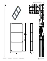
Page 62: ...Geniox Air Handling Unit User Manual 3060386 5 1 Roof curb master tables...

Page 63: ...3060386 Geniox Air Handling Unit User Manual Roof curb master tables 5 2...

Page 64: ...Geniox Air Handling Unit User Manual 3060386 5 3 Roof curb master tables...

Page 65: ...3060386 Geniox Air Handling Unit User Manual Roof curb master tables 5 4...

Page 66: ...Systemair NA 8 Rouse Street Tillsonburg ON N4G 5W8 Toll free 800 688 6363...

Reviews: