


GB.COMPACTAHSK.210520
Registered design. The company reserves the right to make design changes without prior notice.
32 www.swegon.com
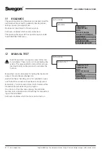
INSTALLATION
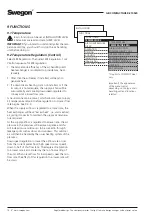
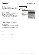
FUNCTIONS
*FUNCTIONS*
TEMPERATURE
AIR FLOW/PRESSURE
FILTER
OPERATION
HEATING
COOLING
IN/OUTPUTS
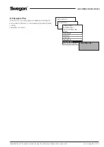
IQnomic Plus
ALL YEAR COMFORT
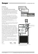
9.7 Cooling(Applies to an air cooler installed
in the outdoor air duct only)
Cooling function 0-10 V and 10-0 V require an IQnomic Plus
module (function selector switch set to position 6). The module
is automatically activated. Wire the cooling connections to the
IQnomic Plus module. See separate instruction TBIQ.
Other functions can be connected to the control unit or the
IQnomic Plus module. If the function is connected to the
IQnomic Plus module, activation will take place automatically.
9.7.1 Operation
Activate the cooling function.
9.7.2 Temperature Regulation (Control)
Stepless 0-10 V DC
Used when variable cooling control is connected. The COMPACT
air handling unit’s cooling controller modulates a 0-10 V DC
signal that is linear with the cooling load.
Both the cooling relays of the unit operate in parallel with the
signal and are energized when the cooling signal exceeds 0.5 V DC
and are de-energized when the signal drops below 0.2 V DC.
Connect the output for Cooling relay 1 and Cooling relay 2 to
terminals 1-2 and 3-4 on the control unit.
Stepless 10-0 V DC
Same as above, but the control signal is inverted where a 10 V
output signal means a 0 % cooling load.
On/off, 1 Step
Used if cooling in one step is connected. The air handling unit’s
cooling controller regulates the cooling load at 0-100 %. Cooling
relays 1 and 2 are energized when the cooling load exceeds 5 %
and are de-energized when the cooling load is less than 2 %.
The output contact for 0-10 V DC control signals operates in paral-
lel with the 0-100 % cooling demand and can be used for indicat-
ing the cooling demand, for instance.
On/off, 2 steps
Used when cooling in 2 steps is connected. The air handling unit’s
cooling controller regulates the cooling load at 0-100 %. Cool-
ing relay 1 is energized when the cooling load exceeds 5 % and is
de-energized when the cooling load is less than 2 %. Cooling relay
2 is energized when the cooling load exceeds 55 % and is de-ener-
gized when the cooling load is less than 50 %.
The 0-10 V DC control signal output operates in parallel with the
0-100 % cooling demand and can be used for indicating the cool-
ing demand, for instance.
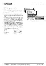
On/off, 3 Steps - Binary
Used when cooling with two inputs controlled with three binary
steps is connected. The cooling controller of the unit regulates the
cooling demand at 0-100 %.
On an increasing cooling load:
Cooling relay 1 is energized when the cooling load is above
5 % and is de-energised when the cooling load is between
40-70 %. Cooling relay 2 is energized when the cooling load is
above 40 %. Cooling relay 1 is energized again (together with
cooling relay 2) when the cooling load is above 70%.
On a decreasing cooling load:
Cooling relay 1 drops when cooling load is below 60 %, it is
energized again when cooling load is below 30 % and drops again
when cooling load is below 2 %. Cooling relay 2 drops when
coolng load is below 30 %.
The output for 0-10 V DC control signals operates in parallel with
the 0-100 % cooling load and can be used for indicating the cool-
ing demand, for instance.
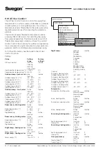
Settings for cooling functions on this page and the next
:
Value
Setting
Factory
range settings
Operation mode
Inactive/active Inactive
Cooling regulation
Stepless 0-10 V On/Off 1 step
Stepless10-0 V
On/Off 1 step
On/Off 2 step
On/Off 3 step binary
Periodic operation
Cooling relay 1
Inactive/pump/ Inactive
pump+valve/valve
Cooling relay 2
Inactive/pump/ Inactive
pump+valve/ valve
Exercise period 1 – 60 min.
3 min.
Interval
1 – 168 hrs.
24 hrs.
Regulation speed
between steps
0-600 sec
300 sec
Outdoor temperature limit
Step 1
0-25 °C
3 °C
Step 2
0-25 °C
5 °C
Step 3
0-25 °C
7 °C
Restart time
0-900 sec
480 sec
Cooling min air flow
Supply air
0-Max flow
–
Extract air
0-Max flow
–
Neutral zone
0-10 °C
2.0 °C
Cooling BOOST
Inactive
Inactive
Comfort
Economy
Sequence
economy
sequence
Start limit in
connection to
min supply air temp
2-10 °C
3 °C
Ramp time
0.5-15%
2.5%
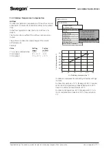
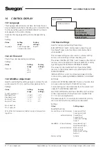
* COOLING *
OPERATION MODE
COOL REGULATION
PERIODIC OPERATION
REGULATION SPEED
OUTDOOR TEMP LIMIT
RESTART TIME
COOL MIN AIR FLOW
NEUTRAL ZONE
COOLING BOOST


