


GB.COMPACTAHSK.210520
Registered design. The company reserves the right to make design changes without prior notice.
30 www.swegon.com
INSTALLATION
FUNCTIONS
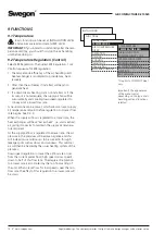
*FUNCTIONS*
TEMPERATURE
AIR FLOW/PRESSURE
FILTER
OPERATION
HEATING
COOLING
IN/OUTPUTS
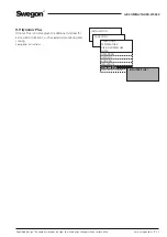
IQnomic Plus
ALL YEAR COMFORT
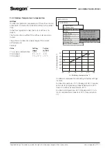
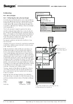
Connection principle for the defrosting function
with separate pressure transducer.
+
-
Nipple
Hose
Extract air duct of
the air handling unit
9.6 Heating
9.6.1 Heat exchanger
9.6.1.1 Defrosting the rotary heat exchanger
In environments where the extract air can occasionally be
humid, the defrosting function can be activated to protect
the heat exchanger from frosting. The function continu-
ously monitors the condition of the heat exchanger rotor
to prevent condensate from freezing in the rotor passages
and clogging them.
The function requires a separate pressure transducer,
preset for heat exchanger defrosting, is wired to the con-
trol unit inputs for external BUS communication (Internal
BUS-1). Two nipples must be fitted to the sheet metal wall
inside the unit’s extract air duct. See the illustration. Run
hoses through the insulation and connect them to the
pressure sensor’sminus and plus nipples.
See special installation instruction for the TBLZ-1-23-aa
Pressure sensor.
The pressure drop across the rotor must then be calibrated
to establish a reference pressure drop for monitoring pur-
poses. See Section 7.4.3.
When the function is activated the pressure drop across
the heat exchanger is continuously measured and the
value is compared with the calibration value. If the pres-
sure drop exceeds the preset limit value, a defrosting se-
quence is implemented where the rotor speed is gradually
ramped down (ramp time of max. 4 minutes) to the speed
at which the pressure drop across the heat exchanger has
decreased to half of the preset limit value. The rotor speed
can be 0.5 rpm but not slower. During the defrosting op-
eration, warm extract air thaws any possible ice coating. A
time delay of 4 minutes gives the heat exchanger a chance
to dry, before the rotor once again is ramped up (ramp
time max. 4 minutes) to its ordinary speed.
The max. duration of the defrosting operation is 30 min-
utes. If the pressure drop has not decreased within this
max. duration on six occasions during a 24-hour period,
an alarm is tripped.
Note that the heat exchanger performs less efficiently
while defrosting is in progress and that the supply air tem-
perature will decrease downstream of the heat exchanger.
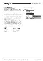
Settings:
Value
Setting
Factory
range settings
Defrosting
Inactive/active Inactive
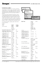
*HEAT*
HEAT EXCHANGER
HEATING BOOST


