background image

33


WIFI PAGE

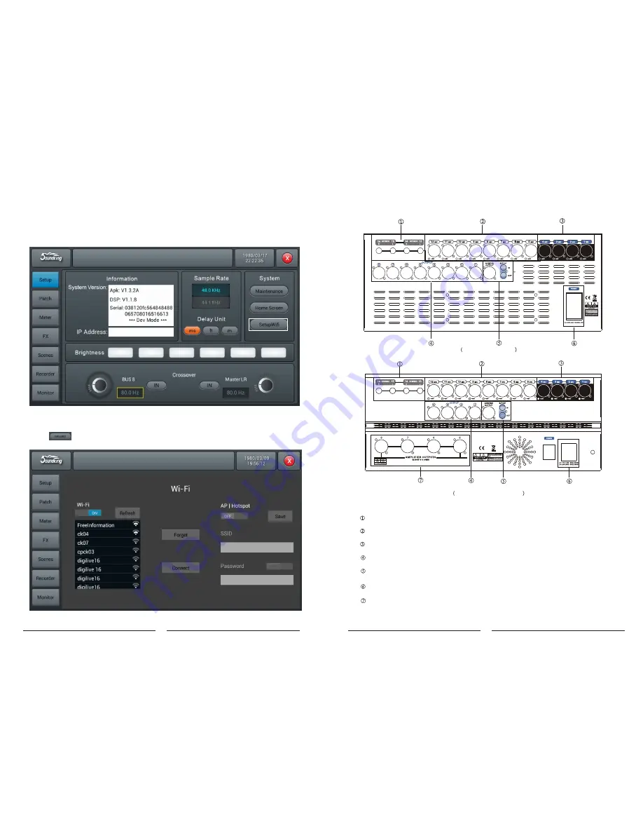
  Setting Mode One of IPAD WIFI Connecting Mixer

  Firstly, please make sure you have plugged the WIFI module attached into the USB port of mixer.

  1. Click 

“S

etup

 on the panel of mixer, enter SETUP tab page.

Mixer Setting

2. Click             on the screen to enter WIFI setting page.


Balanced output, XLR 7/8 is preset as main L/R output


S/PDIF in/out


AC input


 2 Stereo input


 8 XLR MIC input


 4 Combo input

 Internal AMP output

DB20P rear pane

DB20P-600 rear panel

6


Summary of Contents for SDK-DM20

Page 1: ...ed to SOUNDKING No part of this manual may be reproduced translated or photocopied by any means for any purpose without the written permission of SOUNDKING The information involved in this manual is s...

Page 2: ...phone Input channel function Line output Internal signal generator white noise sine wave pink noise Phantom power 48V each channel switchable alone USB function Screen max support 192KHz 24 bit AD DA...

Page 3: ...full functioncompact digital mixer from Soundkingthat features premium hardware touch operation iPad remote control the 4th generation SHARC floating point processor 24bit 192kHz AD DA conversion 8 ef...

Page 4: ...all buttons can not work The screen turns black Press again to exit the lock function Fig Mixer panel 36 5 3 Open the APP just downloaded 5 4 Click shown above to search find Console click If many Co...

Page 5: ...level Bus 1 Bus 8 LR After entering SENDS MUTE switch is the switch to turn on off Send BUS function SOLO is to send quickly set 0 function The channel strip with SELECT SOLO MUTE ON and motorized fad...

Page 6: ...8 SEND fader send mode button when system rests on IN1 or IN2 and one certain channel is selected by pressing SEL Press SENDS physical fader can adjust the bus send level of this channel Bus1 Bus8 LR...

Page 7: ...into the USB port of mixer 1 Click Setup on the panel of mixer enter SETUP tab page Mixer Setting 2 Click on the screen to enter WIFI setting page Balanced output XLR 7 8 is preset as main L R output...

Page 8: ...f SOLO button then the channel feeds monitor with AFL or PFL signals Press once to enable SOLO press again to disable it PFL monitors pre fader signal which is not subject to control of faders and mut...

Page 9: ...turning the main Encoder on the control panel or on the touch screen fine tuning can be activated when pressed the knob down The delay ranges from 0ms to 200ms while the default is 0ms HPF Press to e...

Page 10: ...exported individually or multiply Then single press Export button If export successfully system prompts Export success press Confirm to export selected scenes to USB disk If USB disk cannot be found...

Page 11: ...start from 0 5 ms to 100 ms with default 3 ms Release time of release from 2 ms to 2 s with default 350 ms compatible with many kinds of sound source Depth adjust attenuation of signals lower than the...

Page 12: ...t right selection button to choose FX module Modul1 Modul2 Delay1 Delay2 Reverb 1 Reverb2 GEQ1 GEQ2 Type Single press dropdown button then choose a wanted type from the dropdown list Hall Bright Hall...

Page 13: ...ging the slider or turning the main Encoder on the control pane Double press the parameter frame toset it back to default Send level control Control the level of signal by drag the slider up and down...

Page 14: ...coder on the control panel fine tuning can be activated by pressing the main Encoder knob Tempo ranges from 40 to 240 BPM with a default 80 Adjust the Tempo by turning the main Encoder fine tuning can...

Page 15: ...n the touch screen fine tuning can be activated by pressing the main Encoder knob Pre Delay configure time of Pre Delay ranges from 0 100ms with a default 0ms Adjust the time parameter by turning the...

Page 16: ...panel 15 Channel Switch Single press the button to switch between previous or next channel on the same layer SUM When only one connector Left or right of stereo is plugged single press the button to...

Page 17: ...press the SEL of Bus 1or Bus 2 then the bus page will move right and shows the channel info of Bus 1 Bus 8 The output busses processing channel consists of 4 modules Input Stage EQ Input Source and Ou...

Page 18: ...o the physical output Please refer to the page of Patch for operation of assigning busses to physical outputs 22 2 Patch page This page is mainly for selecting busses to be assigned to 8 analogue outp...

Page 19: ...the module forcibly now Yes or No Maintenance page 21 2 3 5 6 4 7 8 Update from USB Single press Update from USB button a dialog pops up After the update the System will reboot automatically Are you s...

Page 20: ...i Remote Brightness and Time Date Scenes Shows the name of scenes Information System Version shows the version ofAPK DSP Fader and other softwares on this console IPAddress shows the IP address of the...

Reviews: