background image

Specifications

C - 2 Specifications

C

Feature

Specification

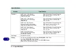
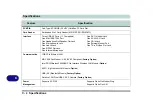
Processor

Intel® Core™ 2 Duo Processor
(478-pin) Micro-FC-PGA Package

T7200/ T7400/ T7600

65nm (65 Nanometer) Process Technology
4MB On-die L2 Cache & 667MHz FSB
2.0/ 2.16/ 2.33


GHz

Intel® Core™ 2 Duo Processor
(478-pin) Micro-FC-PGA Package

T5500/ T5600

65nm (65 Nanometer) Process Technology
2MB On-die L2 Cache & 667MHz FSB
1.66/ 1.83


GHz

Intel® Core™ Duo Processor
(478-pin) Micro-FC-PGA Package

T2300

T2400

T2500

T2600

T2700

65nm (65 Nanometer) Process Technology
2MB On-die L2 Cache & 667MHz FSB
1.66/ 1.83/ 2.0/ 2.16/ 2.33


GHz

Intel® Core™ Solo Processor
(478-pin) Micro-FC-PGA Package

T1300

T1400

65nm (65 Nanometer) Process Technology
2MB On-die L2 Cache & 667MHz FSB
1.66/ 1.83


GHz

Intel® Celeron® M Processor
(478-pin) Micro-FCPGA Package

410

420

430/ 440/ 450

65nm (65 Nanometer) Process Technology
1MB On-die L2 Cache & 533MHz FSB
1.46/ 1.60/ 1.73/ 1.86/ 2.0 GHz

Core Logic

Intel 945GM + ICH7-M

Memory

Two 200 Pin SO-DIMM Sockets Supporting 

DDRII 

(

DDR2

) 533/667 MHz

64-bit Wide 

DDRII

 (

DDR2

) Data Channels

Memory Expandable up to 2GB (256/ 512/ 1024 MB 

DDRII

 Modules)

(

Note

: Do Not Use Other Module Types)

Summary of Contents for M521N

Page 1: ......

Page 2: ......

Page 3: ...ication except for copies kept by the user for backup purposes Brand and product names mentioned in this publication may or may not be copyrights and or registered trade marks of their respective comp...

Page 4: ...n If this equipment does cause harmful interference to radio or television reception which can be determined by turning the equipment off and on the user is encouraged to try to correct the interferen...

Page 5: ...the telephone to report a gas leak in the vicinity of the leak 4 Use only the power cord and batteries indicated in this manual Do not dispose of batteries in a fire They may explode Check with local...

Page 6: ...nd of heating ele ment This is an electrical appliance If water or any other liquid gets into it the computer could be badly dam aged Do not expose the computer to any shock or vibration Do not place...

Page 7: ...d don t forget to save your work Remember to periodically save your data as data may be lost if the battery is depleted 5 Take care when using peripheral devices Do not turn off the power until you pr...

Page 8: ...rician install one When you want to unplug the power cord be sure to disconnect it by the plug head not by its wire Make sure the socket and any extension cord s you use can support the total current...

Page 9: ...from and promptly dispose of a damaged battery Always dispose of batteries carefully Batteries may explode or leak if exposed to fire or improperly handled or discarded Keep the battery away from meta...

Page 10: ...hen refer servicing to qualified service personnel under any of the following conditions When the power cord or AC DC adapter is damaged or frayed If the computer has been exposed to rain or other liq...

Page 11: ...ut the notebook in its carrying bag and secure it with the bag s straps 7 If you re taking any peripherals e g a printer mouse or digital camera pack them and those devices adapters and or cables 8 An...

Page 12: ...ta Pass your computer and disks around the devices Ask security officials to hand inspect them you may be asked to turn it on Note Some airports also scan luggage with these devices Fly safely Most ai...

Page 13: ...ms wrists and hands in a relaxed position Your knees should be slightly higher than your hips Place your feet flat on the floor or on a footrest if necessary Use a chair with a back and adjust it to s...

Page 14: ...n the display to avoid glare or reflections from overhead lighting or outside sources of light Keep the display screen clean and set the brightness and contrast to levels that allow you to see the scr...

Page 15: ...rs 1 6 Hot Key Buttons Keyboard 1 7 Function Keys 1 8 System Map Front Rear Views 1 9 System Map Left View 1 10 System Map Right View 1 11 System Map Bottom View 1 12 Windows XP Start Menu Control Pan...

Page 16: ...r 3 10 Proper handling of the Battery Pack 3 11 Battery FAQ 3 12 Drivers Utilities What to Install 4 1 Module Driver Installation 4 1 Service Packs 4 3 Authorized Driver Message 4 4 Version Conflict M...

Page 17: ...Security Menu 5 11 Fixed disk boot sector Security Menu 5 11 Boot Menu 5 12 Exit Menu 5 13 Upgrading The Computer Overview 6 1 When Not to Upgrade 6 2 Removing the Battery 6 3 Upgrading the Hard Disk...

Page 18: ...Port A 3 RJ 11 Phone Jack A 3 RJ 45 LAN Jack A 3 Security Lock Slot A 3 S PDIF Out Jack A 4 7 Pin S Video Out Jack A 4 USB 2 0 1 1 Ports A 4 Optional Port Replicator Ports and Jacks A 5 DC In Jack A 5...

Page 19: ...deo Adapter C 3 Storage C 3 Audio C 3 Keyboard Pointing Device C 3 PCMCIA C 4 Card Reader C 4 Interface C 4 Communication C 4 Power Management C 4 Power C 5 Environmental Spec C 5 Dimensions Weight C...

Page 20: ...XVIII Preface...

Page 21: ...hapter 4 The installation of the drivers and utilities essential to the operation or improvement of some of the computer s subsystems Chapter 5 An outline of the computer s built in software or BIOS B...

Page 22: ...t Guide should be enough to get you up and running Eventually you should try to look through all the documentation more detailed descriptions of the functions setup and system controls are covered in...

Page 23: ...m Drivers If you are installing new system software or are re configuring your computer for a different system you will need to install the drivers listed in Drivers Utilities on page 4 1 Drivers are...

Page 24: ...o the AC DC adapter Note If you have included the Port Replicator in your purchase option see page 7 15 5 Raise the lid LCD to a comfortable viewing angle and press the power button to turn the comput...

Page 25: ...Buttons 9 LED Power Communication Indicators 10 Built In Microphone Wireless Device Operation Aboard Aircraft The use of any portable electronic transmission de vices aboard aircraft is usu ally prohi...

Page 26: ...cription Green Hard Disk Activity Green Number Lock Activated Green Caps Lock Activated Green Scroll Lock Activated Icon Color Description Green The Computer is On Blinking Green The Computer is in St...

Page 27: ...Keys to allow you to change operational features instantly see Figure 1 3 Figure 1 3 Keyboard Hot Key Function Activate the Default E Mail Program Activate the Default Internet Browser Press to Activa...

Page 28: ...amera Power Toggle Fn F4 Sleep Toggle Suspend Fn F11 Wireless LAN Power Toggle Fn F5 Decrease Audio Volume Fn F12 Bluetooth Power Toggle Fn F6 Increase Audio Volume Fn NumLk Number Lock Toggle Fn F7 D...

Page 29: ...4 7 Pin S Video Out Jack 5 RJ 11 Phone Jack 6 Battery Slot Battery Removed 7 Security Lock Slot 4 in 1 Card Reader The card reader allows you to use the most popular digital storage card formats MMC M...

Page 30: ...outlet s while the computer is in use Figure 1 5 Left View 1 DC In Jack 2 External Monitor Port 3 Mini IEEE 1394 Port 4 RJ 45 LAN Jack 5 Vent Fan Intake Outlet 6 2 USB 2 0 Ports 7 PC Card Slot see pag...

Page 31: ...is cannot be altered even if you change your operating system or you use the module in another computer 4 5 6 3 2 7 CD Emergency Eject If you need to manually eject a CD DVD e g due to an unexpected p...

Page 32: ...ing it Completely dis charge and charge the battery at least once ev ery 30 days or after about 20 partial discharges See Battery Informa tion on page 3 9 for full instructions CPU The CPU is not a us...

Page 33: ...cking the Start menu and selecting Properties from the menu In many instances throughout this manual you will see an instruction to open the Control Panel The Control Panel is accessed from the Start...

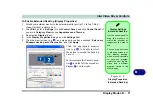
Page 34: ...in Screen resolution Figure 1 9 on page 1 15 5 Click the arrow and scroll to the preferred setting in Color quality Figure 1 9 on page 1 15 6 Click Advanced button Figure 1 9 on page 1 15 to bring up...

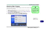
Page 35: ...y Mode Description Single Mode One of the connected displays is used as the display device Intel R Dual Display Clone Mode Both connected displays output the same view and may be configured independen...

Page 36: ...her Stand by or Hibernate mode to conserve power throughout the system enable Hibernate support from the control panel as pictured in Figure 1 10 Pay at tention to the instructions on battery care in...

Page 37: ...res Components Overview Read this chapter to learn more about the following main features and components of the computer Hard Disk Drive Optical CD DVD Device 4 in 1 Card Reader PC Card Slot TouchPad...

Page 38: ...cessible from the bottom of your computer as seen below For fur ther details see Upgrading the Hard Disk Drive on page 6 4 Power Safety Before attempting to ac cess any of the internal components of y...

Page 39: ...el side facing up use just enough force for the disc to click onto the tray s spindle Gently push the CD DVD tray in until its lock clicks and you are ready to start The busy indicator will light up w...

Page 40: ...her materials to the surface of the disc Do not store or place the CD or DVD in high temperature areas Do not use benzene thinner or other cleaners to clean the CD or DVD Do not bend the CD or DVD Do...

Page 41: ...egional Coding Region Geographical Location 1 USA Canada 2 Western Europe Japan South Africa Middle East Egypt 3 South East Asia Taiwan South Korea The Philippines Indonesia Hong Kong 4 South Central...

Page 42: ...ccessed in the same way as your hard disk s Make sure you install the PCMCIA Card Reader Card driver see PCMCIA Card Reader on page 4 9 MMC MultiMedia Card SD Secure Digital MS Memory Stick MS Pro Mem...

Page 43: ...A Card Reader on page 4 9 Inserting and Removing PC Cards Align the PC Card with the slot and push it in until it locks into place To remove a PC Card simply press the eject button next to the slot PC...

Page 44: ...age 4 9 you can configure the functions by double clicking the TouchPad driver icon in the taskbar You may then configure the TouchPad tapping buttons scrolling pointer motion and sensitivity options...

Page 45: ...bar control panel this will bring up the Realtek Audio Configuration menus The volume may also be adjusted by means of the Fn F5 F6 key combi nation Sound Volume Adjustment How high the sound vol ume...

Page 46: ...the printer s USB cable to one of the USB ports on the computer 5 Windows will identify the printer and either load one of its own drivers or ask you to supply one Follow the on screen instructions Pa...

Page 47: ...mation Advanced Configuration and Power Interface The ACPI interface provides the computer with enhanced power saving techniques and gives the operating system OS direct control over the power and the...

Page 48: ...DC adapter see sidebar if you are using the optional Port Replicator 3 Raise the lid LCD to a comfortable viewing angle 4 Press the power button to turn On Battery The battery allows you to use your...

Page 49: ...eature Shutdown Note that you should al ways shut your comput er down by choosing the Turn Off Computer command from the Start menu in Windows This will help prevent hard disk or system prob lems Forc...

Page 50: ...sk motor to turn off if the hard disk drive has not been accessed for a specified period of time if the system reads or writes data the hard disk motor will be turned back on The schemes may also be s...

Page 51: ...rmance especially under DC battery power Choose the Home Office Desk scheme for maximum performance when the com puter is powered from an AC power source Choose the Max Battery scheme bear in mind tha...

Page 52: ...te mode and Shutdown are the same in that the system is off and you need to press the power button to turn it on Their main difference is When you come back from hibernation you can return to where yo...

Page 53: ...f your information on a part of the HDD be fore it turns the system off Although it saves the most power it takes the longest time to return to full operation You can set your computer to automaticall...

Page 54: ...the LED will be off battery or orange AC DC adapter If you are in a power saving mode set to save power through individual components e g hard disk monitor the LED will remain green Figure 3 3 Power...

Page 55: ...pon many factors including the pro grams you are running and peripheral devices attached Power Options you may set low battery Alarms and actions and check the Power Meter from the Power Options contr...

Page 56: ...everal hours to fully recharge the battery When the computer is turned off but plugged into an electrical outlet battery charge time is less Refer to LED Indica tors on page 1 6 for information on the...

Page 57: ...notice any physical defects e g the battery is bent out of shape after being dropped or any unusual smells emanating from the notebook battery shut your computer down immediately and contact your serv...

Page 58: ...nclick the tickboxes see 3 9 and Schemes change all the settings to Never see page 3 4 As the battery nears the end of its life save and close any critical files How do I fully charge the battery When...

Page 59: ...appropriate driver or utility during oper ating system installation Instead you need to manually install some system required drivers and utilities What to Install The Device Drivers Utilities User s...

Page 60: ...tup the same way and some computers have the CD listed under a different drive let ter e g if you have two hard drives or hard disk parti tions one may be designated as Drive C and the other as Drive...

Page 61: ...installed Windows XP Service Pack 2 Make sure you install Windows XP Service Pack 2 or a Windows XP version which includes Service Pack 2 before installing any drivers Service Pack 2 includes support...

Page 62: ...pdate reinstall individual drivers it may be necessary to uninstall the original driver To do this go to the Control Panel in the Windows OS and double click the Add Remove Programs item If you see th...

Page 63: ...Screen 1 1 Check the driver installation order from Table 4 1 on page 4 6 the drivers must be installed in this order which is the same as that listed in the Drivers Installer menu below 2 Click to s...

Page 64: ...Driver Installation If you wish to install the drivers manually click the Exit button to quit the Drivers Installer application and then follow the manual installation procedure for each driver The ma...

Page 65: ...Yes OR Click Start menu Run and navigate Browse to one of the following D Drivers 01VGA Setup exe and click OK 2 To continue click Next Yes 3 Click Finish to restart the computer Audio 1 Click 3 Insta...

Page 66: ...tup exe and click OK 2 Click OK OK 3 The modem is now ready for configuration LAN 1 Click 5 Install LAN Driver Yes OR Click Start menu Run and navigate Browse to D Drivers 04LAN Setup exe and click OK...

Page 67: ...lined in TouchPad and Buttons Mouse on page 2 8 PCMCIA Card Reader 1 Click 7 Install PCMCIA Driver Yes OR Click Start menu Run and navigate Browse to D Drivers 06PCMCIA setup exe and click OK 2 Click...

Page 68: ...SB WLAN Module on page 7 4 PC Camera See install procedure in PC Camera Driver Installa tion on page 7 7 Bluetooth See install procedure in Bluetooth Driver Installa tion on page 7 13 Port Replicator...

Page 69: ...s found in Setup Even if you are a beginner keep a record of the set tings you find and any changes you make This information could be useful if your system ever needs servicing There is one general r...

Page 70: ...operating system Once that starts you can t get into Setup without rebooting POST Screen 1 BIOS information 2 CPU type 3 Memory status 4 Enter Setup prompt appears only during POST Note The POST scre...

Page 71: ...or authorized service center as soon as possible Non Fatal Errors This kind of error still allows you to boot You will get a message identifying the problem make a note of this message followed by the...

Page 72: ...p turn on the computer and press F2 during the POST The prompt Press F2 to Enter Setup seen in Figure 5 1 on page 5 2 is usually present for a few seconds after you turn on the system If you get a Key...

Page 73: ...If these tools are confusing press F1 to call up a General Help screen and then use the arrow keys to scroll up or down the page The Item Specific Help on the right side of each screen explains the h...

Page 74: ...er data files to reflect these changes Figure 5 2 Main Menu PhoenixBIOS Setup Utility Main Advanced Security Boot Exit F1 Help Select Item Change Values F9 Setup Defaults Esc Exit Select Menu Enter Se...

Page 75: ...ration of hard disks and CD DVD device s on the computer s IDE Channels Use the Auto Type setting to have the items configured automatically for you System Extended Memory Main Menu This item contains...

Page 76: ...up Utility Main Advanced Security Power Boot Exit F1 Help Select Item Change Values F9 Setup Defaults Esc Exit Select Menu Enter Select Sub Menu F10 Save and Exit Item Specific Help Chipset Informatio...

Page 77: ...ial Bus Boot time Diagnostic Screen Advanced Menu Use this menu item to enable disable the Boot time Diagnostic Screen or POST screen see The Power On Self Test POST on page 5 2 Power On Boot Beep Adv...

Page 78: ...access to your ma chine as it boots up af ter you turn it on These settings do not affect your machine or network passwords which will be set in your software OS Figure 5 4 Security Menu PhoenixBIOS...

Page 79: ...password without typing any password entry and Enter again to confirm the password clearance Fixed disk boot sector Security Menu If you choose Write Protect this will protect against viruses being wr...

Page 80: ...5 5 Boot Menu PhoenixBIOS Setup Utility Main Advanced Security Exit F1 Help Select Item Change Values F9 Setup Defaults Esc Exit Select Menu Enter Select Sub Menu F10 Save and Exit Item Specific Help...

Page 81: ...s original state and erase any previous changes you have made in a previous session Figure 5 6 Exit Menu PhoenixBIOS Setup Utility Main Advanced Security Boot Exit F1 Help Select Item Change Values F9...

Page 82: ...BIOS Utilities 5 14 5...

Page 83: ...r slotted flathead screwdriver An antistatic wrist strap Before working with the internal components you will need to wear an antistatic wrist strap to ground yourself because static electricity may d...

Page 84: ...ade your computer by replacing the existing processor with a fast er new one you will need to contact your customer service representative We rec ommend that you do not do this yourself since if it is...

Page 85: ...turn it over 2 Slide the latch in the direction of the arrow it will remain in place 3 Slide the latch in the direction of the arrow and hold it in place 4 Slide the battery out of the computer in th...

Page 86: ...turn it over and remove the battery 2 Locate the hard disk bay cover and remove screw 3 Carefully lift the hard disk assembly up out of the bay at point and disconnect the cable at point HDD System W...

Page 87: ...Computer Upgrading the Hard Disk Drive 6 5 6 4 Remove screws to release the hard disk from the assembly cover and reverse the process to install any new hard disk Figure 6 3 Hard Disk Assembly Remova...

Page 88: ...he Optical CD DVD Device 6 Upgrading the Optical CD DVD Device 1 Turn off the computer and turn it over and remove the battery 2 Locate the component bay cover and remove screws Figure 6 4 Removing th...

Page 89: ...ide of the cover lift up the component bay cover 4 Carefully disconnect the fan cable and remove the cover 5 Remove the optical device screw 6 Use a screwdriver to carefully push out the optical devic...

Page 90: ...DIMM DDRII DDR2 type memory modules see Memory on page C 2 for details of supported module types The total memory size is automatically detected by the POST routine once you turn on your computer 1 Tu...

Page 91: ...ached to the under side of the cover lift up the component bay cover 4 Carefully disconnect the fan cable and remove the cover 5 Gently pull the two release latches on the sides of the memory socket 9...

Page 92: ...FORCE the module it should fit without much pressure 10 Press the module in and down towards the mainboard until the slot levers click into place to secure the module 11 Replace the cover and make su...

Page 93: ...configuration purchased If you are unsure please contact your service representa tive Intel PRO Wireless WLAN Module 802 11 b g USB WLAN Module PC Camera Module Bluetooth Module Port Replicator Module...

Page 94: ...you install the drivers in the order indicated in Table 4 1 on page 4 6 To get help on the network settings you can view the User Guide from the Intel PROSet Wireless menu Wireless Device Operation Ab...

Page 95: ...icense and click Next Next OK 5 Click OK to complete the installation 6 You can configure the settings by going to the Intel R PROSet Wireless control panel Start Programs All Programs Intel PROSet Wi...

Page 96: ...click 1 Wireless Lan Yes 3 Choose the language you prefer and click OK 4 Click Next 5 Click Finish to complete the installation 6 The operating system is the default setting for Wireless LAN control i...

Page 97: ...ule 7 5 7 Network Connection Use the Windows Net work Connections con trol panel to access available wireless net works Start Settings Network Connections or Start Connect To Show all Connections Figu...

Page 98: ...ated in Table 4 1 on page 4 6 Taking Still Pictures You may take still pic tures in the Windows XP operating system See PC Camera Hot Key on page 7 12 for instructions on using the PC Camera hot key t...

Page 99: ...VD drive click Cancel if you see a New Hardware Found message 2 Click Optional and then click 2 PC Camera Web cam Yes 3 Click Next 4 Click Finish OK to restart the computer 5 Press the Fn F10 key comb...

Page 100: ...Windows 1 Go to the Start menu and point to Settings or just click Control Panel and click Control Panel then double click the Sounds Audio Devices icon Sounds Speech and Audio Devices in Category Vi...

Page 101: ...ice menu 5 Click Recording button 6 Click Mic Volume check box if it is not checked then click OK 7 The Recording Control window will pop up 8 Boost the Recording volume as high as it will go 9 Close...

Page 102: ...o to the File menu and select Save Captured Video choose a file name and location and then click Open you can view the file using the Windows Media Player Set Capture File In the EMAMCAP program you w...

Page 103: ...AP program is flickering you can try to adjust the setting in the Lighting Selection options 1 Run the EMAMCAP program 2 Go to Options and scroll down to select Video Capture Filter 3 Click Video Imag...

Page 104: ...ombination to power on the camera 2 Press the PC Camera hot key once 3 The EMAMCAP application will run To take a still picture 4 Press the PC Camera hot key once to take the picture 5 Select File Sav...

Page 105: ...v2 12 4 Choose the language you prefer and click OK 5 Click Next 6 Click the button to accept the license agreement and then click Next 7 Click Next Next Install 8 Click Finish Yes to restart the comp...

Page 106: ...7 9 Bluetooth Control Panel User Guides User Guide View the BlueSoleil User Guides from the Help Menu or press the F1 key in the IVT Cor poration BlueSoleil Main Window The Manual in Adobe pdf format...

Page 107: ...e 7 16 for configuration information Port Replicator AC DC Adapter You will be provided with a 90W AC DC adapter if you purchase the port replicator op tion If you are using the com puter with the Por...

Page 108: ...PLICATOR see Port Replicator Module on page 7 15 5 Turn ON the computer 6 Install the serial port driver see below 7 Install the LAN driver see page 7 17 8 Plug in any devices you require into the app...

Page 109: ...rt menu then point to but don t click it just highlight it My Computer Right click it to make the sub menu appear and scroll down to Properties and click on it go to step 5 5 Click Hardware tab and th...

Page 110: ...Modules Options 7 18 7...

Page 111: ...es make sure you have followed the instructions carefully and observed the safety precautions in the preface If all else fails talk to your service representative You should also make a record of what...

Page 112: ...tions anywhere Power Savings Make sure that the system is not in Hibernate or Stand by mode by pressing the keys con figured in your Power Management Power Options see Configuring the Power Button on...

Page 113: ...ams to run at times when you are not using your computer You can use those that are provided free with your OS or buy the more powerful dedicated programs to do so Write down your passwords and keep t...

Page 114: ...don t know Viruses are often triggered from within e mail attachments so take care when opening any attached file You can configure most Anti Virus pro grams to check all e mail attachments Note You...

Page 115: ...looking at the computer s manual but what about any new peripheral devices you have just purchased Many problems are caused by the installation of new hardware and or software Always refer to the doc...

Page 116: ...ings The less you have to deal with then the easier the source of the problem may be found Example if your computer has many devices plugged into its ports and a number of programs running then it wil...

Page 117: ...up immediately turn it off then on again You are losing battery power too quickly The system is using too much power If your OS has a Power Options scheme see Power Schemes on page 3 4 check its sett...

Page 118: ...pter Make sure that your notebook is completely powered off before putting it into a travel bag or any such container Putting a notebook which is powered on in a travel bag may cause the Vent Fan inta...

Page 119: ...he screen saver is activated Press any key or touch the TouchPad No image appears on the external monitor I have plugged in and powered on You haven t installed the video driver and configured it appr...

Page 120: ...compact disc is not correctly placed in the tray Gently try to remove the disc using the eject hole see Loading Discs on page 2 3 The DVD regional codes can no longer be changed The code has been chan...

Page 121: ...k the LED indicator to see if the WLAN Bluetooth module is on or off see LED Indicators on page 1 6 If the LED indicator is off then press the Fn F11 WLAN or Fn F12 Bluetooth key combination s in orde...

Page 122: ...Troubleshooting 8 12 8...

Page 123: ...Ports Jacks A 1 A Appendix A Interface Ports Jacks Overview The following chapter will give a quick description of the interface ports jacks which allow your computer to communicate with external devi...

Page 124: ...ck Plug the supplied AC DC adapter into this jack to power your computer External Monitor VGA Port This port allows you to connect an external monitor or Flat Panel Display to get dual video or simult...

Page 125: ...o the built in modem You may plug the telephone line directly into this RJ 11 telephone connection Note Broadband e g ADSL modems usually connect to the LAN jack RJ 45 LAN Jack This port supports LAN...

Page 126: ...eo cable to make the connection Enable this port from the video driver controls USB 2 0 1 1 Ports These USB 2 0 compatible ports USB 2 0 is fully USB 1 1 compliant are for low speed peripherals such a...

Page 127: ...itor or Flat Panel Display to get dual video or simultaneous display on the LCD and external monitor FPD see Display Devices on page B 6 Parallel Port Connect a parallel type printer to this port The...

Page 128: ...boards mice or scanners and for high speed peripherals such as external HDDs digital video cameras or high speed scanners etc Devices can be plugged into the computer and unplugged from the computer w...

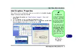
Page 129: ...Intel Video Driver Installation Make sure you install all the drivers in the order indicated in Table 4 1 on page 4 6 Instructions for installing the video driver are repeated below 1 Click 2 Install...

Page 130: ...system DVMT Notes The default memory set ting is 128MB and this may be adjusted to ei ther 64MB or 224MB See Total Graphics Memory Advanced Menu on page 5 9 DVMT is not local video memory DVMT will no...

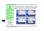
Page 131: ...Graphics Properties button 3 You can also access Graphics Properties from the Windows Intel R GMA Driver for Mobile control panel or from the taskbar icon Taskbar Icon You can also access the controll...

Page 132: ...ties of the computer and see the Support tab in Information to get weblinks to the latest information on the Intel Website Figure B 3 IntelGraphicsMedia Accelerator Driver for mobile Control Panel Tab...

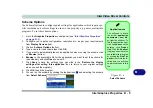
Page 133: ...rowse button 6 Browse to the executable file for the application you want to set the scheme for see sidebar and click Open to select it 7 Click Save to save the settings you can click in the Restore t...

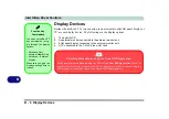
Page 134: ...A TV connected to the 7 Pin S Video Out Jack Function Key Combination You can use the Fn F7 key combination to tog gle through the display options Notebook Only External Display Only Notebook External...

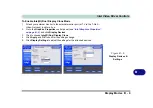
Page 135: ...rnal monitor port or TV to the 7 Pin S Video Out Jack and turn it on 2 Go to the Graphics Properties control panel see Intel Graphics Properties on page B 3 and click Display Devices 3 Click to choose...

Page 136: ...color quality etc Use this feature to display the screen through a projector for a presentation Extended Desktop This mode allows a desktop to span multiple displays and acts as a large workspace This...

Page 137: ...he 7 Pin S Video Out Jack and turn it on 2 Go to the Graphics Properties control panel see Intel Graphics Properties on page B 3 and click Display Devices 3 Click to choose Intel R Dual Display Clone...

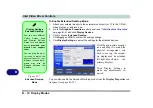
Page 138: ...also enable the Extended Desktop mode from the Display Properties con trol panel see page B 11 Figure B 7 Extended Desktop Mode Display Settings Extended Desktop You can have different Colors Screen...

Page 139: ...make sure you have checked Extend my Windows desktop onto this monitor and click Apply Figure B 8 Display Properties Extended Desktop Display Settings Extended Desktop Use the control panel to drag t...

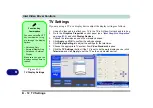
Page 140: ...vices 4 Click Apply and OK to confirm the settings change 5 Click Display Settings to adjust the settings for the television 6 Choose the appropriate TV system from Video Standard dropbox 7 Click the...

Page 141: ...rmation The specifications listed in this Appendix are correct at the time of going to press Certain items particularly processor types speeds and CD DVD device types may be changed updated or delayed...

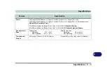
Page 142: ...00 T2700 65nm 65 Nanometer Process Technology 2MB On die L2 Cache 667MHz FSB 1 66 1 83 2 0 2 16 2 33 GHz Intel Core Solo Processor 478 pin Micro FC PGA Package T1300 T1400 65nm 65 Nanometer Process Te...

Page 143: ...up to 224MB of Video Memory dynamically allocated from system memory where needed Storage Optical Device Drive Bay One Changeable 12 7mm h Optical Device CD DVD Type Drive see Optional on page C 6 fo...

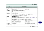
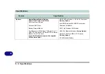
Page 144: ...ernal Microphone One RJ 11 Modem Jack One RJ 45 LAN Jack One DC in Jack One External Monitor Port One 7 Pin S Video Out Jack Communication 1GB PCIe Ethernet LAN MDC 56K Fax Modem V 90 V 92 Compliant F...

Page 145: ...rt Replicator Only 4 Cell Smart Lithium Ion Battery Pack 14 8V 2 4 AH 4S1P Standard Battery 8 Cell Smart Lithium Ion Battery Pack 14 8V 4 4 AH 4S2P Optional Extended Battery Environmental Spec Tempera...

Page 146: ...B 2 0 Ports Serial Port Parallel Port External Monitor Port DC In Jack Note Port Replicator requires the supplied 90W power adapter MDC 56K Fax Modem V 90 V 92 Compliant Factory Option Intel PRO Wirel...

Reviews: