SureCall | 48346 Milmont Drive, Fremont CA 94538 | 1-888-365-6283 | [email protected]
SureCall | 48346 Milmont Drive, Fremont CA 94538 | 1-888-365-6283 | [email protected]
13
12
Alarm Interface, Definitions & Conditions
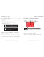
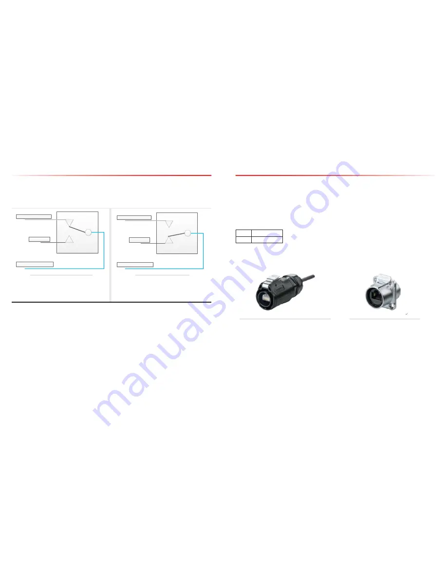
2.8 VSWR Alarm Trigger Criteria
The VSWR Alarm (pins 3 and 6) is triggered under one (or more) of the following:
• VSWR Alarm caused by outdoor or indoor VSWR abnormal
• Repeater power OFF
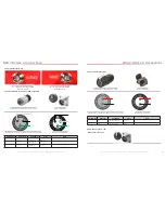
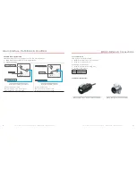
N.C.
N.O.
COM
Relay Shown in Non-‐Alarm Condition
To A2, ALARM I/O, pins6
To A2, ALARM I/O, pins3
No connection
N.C.
N.O.
COM
Relay Shown in Alarm Condition
To A2, ALARM I/O, pins6
To A2, ALARM I/O, pins3
No connection
Relay Shown In Non-Alarm Condition
Relay Shown In Alarm Condition
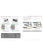
Dry Contact VSWR in Non-Alarm
Relay connection Fig. in Non-Alarm Condition
Contacts pins3 of A2, pins6 of A2 CLOSE
Dry Contact VSWR in Alarm
Relay connection Fig. in Alarm Condition
Contacts pins3 of A2, pins6 of A2 OPEN
BDA Interface & Connections
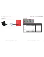
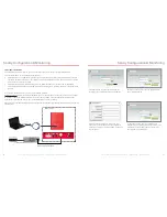
2.10 Ethernet Interface (A4)
Male Connector used to transfer to internet or ethernet
Female Ethernet Port (A4, RJ-45) on BDA
2.9 Load Restrictions
Alarm Dry Contact Output Restrictions
• Maximum switching voltage: 125 VAC, 60 VDC
• Maximum switching current: 1A
External Alarm Input Restrictions
• Maximum repetitive reverse voltage: 28 V
• Impedance load: 470 Ohm
“0” -
0V
“1” -
0.8V - 28V


