background image

SureCall  |  48346 Milmont Drive, Fremont CA 94538  |  1-888-365-6283  |  [email protected]

SureCall  |  48346 Milmont Drive, Fremont CA 94538  |  1-888-365-6283  |  [email protected]

33

32

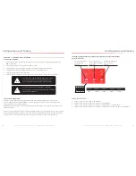
7.3 Hardware Installation

Once the Sentry software is installed, you can proceed to connect and configure the Guardian2 QR BDA. 
To install the hardware, first complete the following steps:
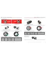
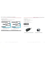
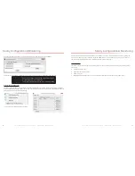
•  USB Connection. Use a USB cable to connect your computer directly to the Guardian2 QR USB port. The USB 

connection on the Guardian 3 QR is accessible by opening the NEMA-4 enclosure. The port is on top of the unit 
inside the enclosure, as shown below.

•  Ethernet Connection. Plug the Ethernet cable into the yellow-capped socket on the bottom of the NEMA-4 

enclosure, labeled Ethernet. The other end of the Ethernet cable goes to the network server or network switch on 
the LAN.

Once the connections are made, power on the Guardian2 QR BDA.
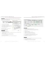
Register an account: Before you install the hardware, you’ll first need to register an account. Connect your computer 
to the network where the Guardian2 QR Ethernet connection was made. A secure LAN connection is important 
because it will allow the computer to “see” the Guardian2 QR device on the network. 
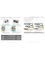
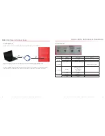
Start the Sentry client application by clicking on the shortcut that resulted from installing the software. You will see the 
screen below:

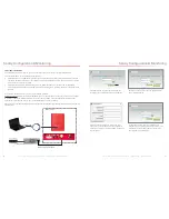
To 

Computer USB

TO NFPA Guardian2's ETHERNET

To  NFPA Guardian2's USB

To  Network server

NFPA Guardian2

 Sentry Configuration & Monitoring

Click Register and you’ll see the following screen, 
prompting you to enter the local Server IP address.

Enter the local Server IP, or you can use SureCall’s 
server IP: 99.55.251.45.

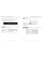
Enter a User Name, Password, E-mail, and User 
Phone in the fields provided. Then click Register to 
proceed. You will the Login screen again, as shown in 
the next screen.

In the fields provided, enter the Username and 
Password that you just registered on the system. This 
will enable you to proceed to device configuration, 
as explained in the steps below:

 Sentry Configuration & Monitoring

Summary of Contents for Guardian2 QR

Page 1: ...SureCall Guardian2 QR Quick Response User and Installation Guide Public Safety Bands BDA for First Responders Supports 700 MHz FirstNet Ready and 800 MHz bands 07 13 2018 ...

Page 2: ...h registration will be available to the public on the same day it is filed with the Commission Registrations may be accessed at www fcc gov signal boosters registration Click on View All Boosters from the Part 90 Signal Booster Registration and Discovery page The registrations can be searched and sorted by booster ID number name of the filer city county state zip code latitude longitude or call si...

Page 3: ...ue to geographical location and or building design Powerful in building BDA with 31dB of adjustable gain level NEMA 4 rated amplifier housing No additional NEMA enclosure required Integrated 7 pin alarm and UPS port for external battery backup Power control maintains maximum output power at 26 dBM Automatic oscillation detection and protection system powers down the BDA to prevent harmful radio in...

Page 4: ...e working in high locations such as roofs and or ladders Follow applicable safety regulations and best practices to avoid falling Take care not to drop objects from any high area Cordon off ground areas directly below the section of roof you are working on or below your ladder whenever possible In addition as a qualified installer you are responsible for knowing and following all applicable codes ...

Page 5: ...o AC 110V 60Hz Male on BDA A5 1 2 3 L N E 1 2 3 L N E Female used to connect to 110VAC or 110V of UPS output Male pinout on BDA A5 Pin Number Definition Full Name Color Note 1 L Live Wire Black 2 N Neutral Wire White 3 E Earth Wire Green 2 4 DC12 20V Interface A9 Female used to transfer to DC 12 20V Male on BDA A9 1 2 DC DC 1 2 D C D C Female used to connect to 110VAC or 110V of UPS output Male pi...

Page 6: ...11 10 2 6 Alarm I O Interface A2 Male Alarm Connector used to transfer to Fire Department Control Box Female Alarm Connector A2 on BDA 1 2 3 4 5 6 7 Dry Contact RF Module Summary Alarm Normally Closed External Alarm IN 2 External Alarm IN 1 Dry Contact VSWR Alarm Normally Closed Dry Contact VSWR Alarm Normally Closed Dry Contact RF Module Summary Alarm Normally Closed External Alarm IN GND 2 1 5 4...

Page 7: ...tion To A2 ALARM I O pins6 To A2 ALARM I O pins3 No connection Relay Shown In Non Alarm Condition Relay Shown In Alarm Condition Dry Contact VSWR in Non Alarm Relay connection Fig in Non Alarm Condition Contacts pins3 of A2 pins6 of A2 CLOSE Dry Contact VSWR in Alarm Relay connection Fig in Alarm Condition Contacts pins3 of A2 pins6 of A2 OPEN BDA Interface Connections 2 10 Ethernet Interface A4 M...

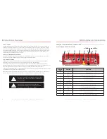
Page 8: ...uipment after initialization unplug the USB cable As shown the NEMA housing must be open to gain access to this port The interface is used to initialize network connections using a computer Be sure to unplug the USB cable after the network initialization is completed TO A7 TO Computer USB Alarm LEDs Definitions Conditions 2 12 Alarm LEDs A8 Status Description Note POWER Green ON Normal OFF Missing...

Page 9: ... and other components Important Installation Safety Precautions The exterior antenna must not be co located or operating in conjunction with any other antenna Always use a properly installed SureCall lightning protector between the exterior antenna and the BDA Always power off the BDA before working on the roof of the building or anywhere in close proximity to the external antenna Comply with all ...

Page 10: ...ation Planning the Installation Planning the Installation horizontally try raising the exterior antenna You may also try reducing the BDA gain as described in Chapter 5 of this manual Antenna Safety Precautions You can mix and match dome and directional antennas as needed to obtain proper coverage throughout the building or area where you need to boost the signal If you use a Yagi exterior antenna...

Page 11: ...e are a few reminders and essential steps A Yagi antenna is mounted horizontally with drip hole facing down and aimed at the desired radio tower line of sight Mount the antenna Connect a length of cable to the antenna and hand tighten Run the cable along the planned route Install a properly grounded SC LP lightning protector Seal any exterior cable entry points on building exterior with caulking o...

Page 12: ...portant to keep the cable runs equal or use taps to ensure a harmonious install CAUTION VERIFY THAT ALL INTERIOR ANTENNAS MEET THE SEPARATION REQUIREMENTS DESCRIBED IN THE PREVIOUS CHAPTER AND THAT NO ANTENNA IS AIMED TOWARD THE EXTERIOR ANTENNA CAUTION DO NOT CONNECT AN INTERIOR ANTENNA TO THE SPLITTER INPUT Installation 4 4 Mounting the BDA Mount the Guardian2 QR as follows Verify that the selec...

Page 13: ...t booster switches with high but not full attenuation as full attentuation would cause the band to shut off DURING CONFUGURATION you may add gain incrementally until the signal level has improved enough to meet safety requirements Note that red flashing lights indicate the system has detected oscillation for the corresponding channel s The band will turn off stop working if adjustments are not mad...

Page 14: ...e in the building As a general rule increasing gain by 6dB doubles the coverage distance of the interior antennas Start at the lowest gain and increase gradually as needed If one or more red Warning lights comes on it indicates there is oscillation in that band and adjustments are needed If you can t get the coverage reasonably well balanced you may need to install an additional interior antenna a...

Page 15: ...software from your device supplier or download the software here http www surecall com product Sentry html Install the software using the steps outlined below Configure the server to a static IP or public IP address In order to function on the network correctly the server and the Guardian2 QR device must be a on the same Local Area Network or b the server must be the front end to the device Use ap...

Page 16: ... as shown below Sentry Configuration Monitoring The above screen confirms the installation folder and shortcut folder where you can access the Sentry software Click Next to proceed with the installation The software will now install A launch icon will be placed on your Desktop When the process is complete you ll should see the Installation Successful screen as shown below This verifies that the Se...

Page 17: ...Before you install the hardware you ll first need to register an account Connect your computer to the network where the Guardian2 QR Ethernet connection was made A secure LAN connection is important because it will allow the computer to see the Guardian2 QR device on the network Start the Sentry client application by clicking on the shortcut that resulted from installing the software You will see ...

Page 18: ... can be connected to the server Dynamic IP is available by checking Auto Search IP function OR OR enter IP parameters manually if the device needs a static IP Click Apply to finish the configuration The following summary screen appears if the booster connects to the server successfully Sentry Configuration Monitoring Column Definitions Attenuation Manually adjusted attenuation via software Manual ...

Page 19: ...DEVICE AND BY SOFTWARE CANNOT EXCEED 25 DB Another feature is E mail Alert meaning that the user will receive an e mail if an alert occurs Modify Booster Information To modify the booster information right click to access a pop up menu with the following additional options Select Edit Booster Info to proceed Sentry Configuration Monitoring Delete Booster To delete a booster right click on the summ...

Page 20: ...lect your device and right click to access a pop up menu with additional options as shown below Select Antenna Position Debug You will see the following Debug Tool screen Sentry Configuration Monitoring Place the antenna in the appropriate position and click Measure to read the current RSSI value Then try putting the antenna in 5 different positions read their respective 5 RSSI values and click Co...

Page 21: ...io or television reception which can be determined by turning the equipment off and on the user is encouraged to try to correct the interference by one or more of the following measures Reorient or relocate the receiving antenna Increase the separation between the equipment and receiver Connect the equipment into an outlet on a circuit different from that to which the receiver is connected Consult...

Page 22: ...Warranty CHAPTER 10 WARRANTY Activate your product warranty at www surecall com For questions regarding your warranty contact a SureCall representative at 1 888 365 6283 or email support surecall com 10 1 Warranty Periods Your warranty includes the following periods Three Year Product Warranty SureCall products are covered under a three year product warranty from the date of purchase This protects...

Page 23: ...SureCall Inc 48346 Milmont Drive Fremont California 94538 USA 888 365 6283 www surecall com ...

Reviews: