SureCall | 48346 Milmont Drive, Fremont CA 94538 | 1-888-365-6283 | [email protected]
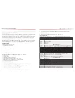
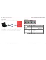
6.2 LED Conditions
LED INDICATIONS
LED
Color
LED
Condition
Resolution
--
OFF
Normal operation. When the light is off, it means things are normal and that the band is active.
Yellow
Solid
Normal operation. The frequency band is not in use. Eventually, the band will enter sleep mode.
Yellow
Flashing
Normal operation. The Automatic Gain Control (AGC) is self-adjusting.
Red
Flashing
The booster is receiving too much signal which can cause the affected band to automatically turn off. If this
happens:
1. Turn the outside Yagi antenna in short increments away from the signal source.
2. Increase the separation between antennas (more vertical separation works best).
3. Add an inline attenuator to the cable connected to the Outside port on the booster.
Red
Solid
The associated frequency band is off. If the red light flashes for a long time (caused by too much signal),
and then turns solid red, it means the associated frequency band has been turned off. This will happen if the
gain dial for that frequency band has been turned all the way down.
Yellow/
Red
Flashes
alternating
colors
Self-oscillation has been prevented.
1. Increase the separation between the inside and outside antennas. If your booster kit uses two
directional antennas (example: outside Yagi antenna and inside panel antenna), ensure that they are
facing away from each other.
2. If the condition continues, increase attenuation in small increments until the light turns off or flashes
yellow.
Refer to your Sentry Monitoring Software for more information about LED codes. Meanwhile, if you have any questions
during setup, please reach out to our U.S.-based support technicians:
Call: 1-888-365-6283
Email: [email protected]
6.3 Testing & Troubleshooting
Once the booster is powered on (and no Warning lights are on), assess the signal in locations of needed signal
improvement. Refine the antenna locations and/or gain levels as needed, then complete the permanent installation
when you are confident the system will perform well
.
A few tips and some perspective:
• It’s not realistic to expect full reception everywhere in the building.
• As a general rule, increasing gain by 6dB doubles the coverage distance of the interior antennas. Start at the
lowest gain and increase gradually as needed.
• If one or more red Warning lights comes on, it indicates there is oscillation in that band and adjustments are needed
• If you can’t get the coverage reasonably well-balanced, you may need to install an additional interior antenna
and/or a different type of interior antenna and/or relocate interior antennas.
SureCall | 48346 Milmont Drive, Fremont CA 94538 | 1-888-365-6283 | [email protected]
27
26
Configuration and Testing
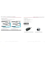
A few practical attenuation examples:
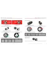
Important Note: Turn ALL uplink attenuations dip switches to ON and adjust them back one step at a time until uplink
connectivity is made with the Emergency Radio Tower.
• Turning all switches OFF = 0 dB attenuation (booster is at full gain).
• Turning ON switch #1 in a bank = 1 dB attenuation (booster maximum gain is reduced by 1 dB).
• Turning ON switches #1, 3, and 5 in a bank = 1+4+16 dB attenuation = 21 dB attenuation. For example, in an 80
dB booster, the selected channel is reduced to 59 dB (80 dB -21 dB).
• Turning ON all switches in a bank = 1+2+4+8+16 dB attenuation = 31 dB attenuation. For example, in an 80 dB
booster, the selected channel is reduced to 49 dB (80 dB-31 dB).
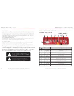
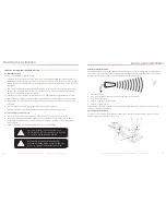
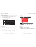
When the BDA is powered on, the green Power Light (3) should illuminate.
• If any of the bands are oscillating, the corresponding band lights (1 and/or 2) will flash red and that band will
eventually shut down if adjustments are not made
.
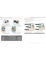
Note: In general, the uplink and downlink DIP switches should be set identically but this is not always the case.
CHAPTER 6: TESTING AND TROUBLESHOOTING
6.1 Band LED Conditions
This section will help you interpret the LED indicators on your Guardian2 QR. But first, here are a few configuration and
testing points to keep in mind:
• If the control light for a specific frequency band is flashing red or red-yellow, try increasing the antenna separation
between the inside and outside antennas as much as possible first, then restarting the booster.
• Avoid setting the gain below 35 dB, as this could cause the affected frequency band to stop amplifying.
1
2
3
Configuration and Testing
NOTE:
TURN ALL UPLINK DIP SWITCHES TO
ON
AND ADJUST THEM
BACK ONE STEP AT A TIME UNTIL UPLINK CONNECTIVITY IS MADE
WITH THE EMERGENCY RADIO TOWER.


