SureCall | 48346 Milmont Drive, Fremont CA 94538 | 1-888-365-6283 | [email protected]
SureCall | 48346 Milmont Drive, Fremont CA 94538 | 1-888-365-6283 | [email protected]
35
34
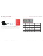
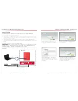
Register the Device. Connect the Guardian2 QR device to the networked client computer with a USB cable as
described in the previous section. Make sure the server is also linked to the computer. Select a serial port and click
Open, as shown in the Add Booster screen below.
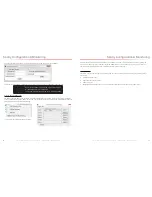
Complete device registration as described below:
• Click Refresh to query device parameters
• Enter a name in the Booster Name field
• Enter the location in the Location Address field (optional)
• Click Add to register the device on the server
• Keep in mind that only the registered user is authorized to
see/operate the added device.
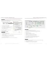
Using the same screen as before, configure the device
according to the steps below.
7.4 Configuring the Booster System
Configure the Device
.
• Select a serial port and click Open.
• Click Refresh to query device parameters
.
• Click on the drop-down menu and select a server IP address and port number to make sure the device can be
connected to the server
.
• Dynamic IP is available by checking Auto Search IP function, OR…
• …OR enter IP parameters manually, if the device needs a static IP.
• Click Apply to finish the configuration.
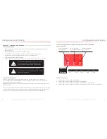
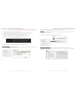
The following summary screen appears if the booster connects to the server successfully:
Sentry Configuration & Monitoring
Column Definitions:
• Attenuation: Manually adjusted attenuation via software.
• Manual Attenuation: Manually adjusted attenuation using controls on the device
.
• Automatic Gain Control: Automatically adjusted attenuation from excessive signal.
• Gain: Current gain.
• Output Power: Current power.
• Outside Signal Strength: Strength of input signal.
• Uplink/Downlink Status: RF band status: Sleep, Active, OFF.
• Over Power: Over
-
power alert status: Red=Alert; Green=Normal.
• Oscillation: Oscillation-alert status: Red=Alert; Green=Normal.
• Over Attenuation: Manual over
-
attenuation status: Red=Alert; Green=Normal.
• Current Status: Over
-
current alert status: Red=Alert; Green=Normal.
• Operation Power: Single RF band power.
Other Definitions:
• Booster Connection: Booster and Sentry module Connection. Red=Disconnection; Green=Normal.
• Sum Power: Sum power of the device
• Device Status: RF status of the device. Red=Alert; Green=Normal.
• Uplink VSWR: Uplink VSWR status. Red=Alert; Green=Normal.
Sentry Configuration & Monitoring

