Chapter 2: Installation
2-7
FA
N
1
JI2C2
JWOR
JFSB3
JF1
JWD
JLED
Battery
J40
DI
M
M
1A
DI
M
M
2A
DI
M
M
1B
I-SATA2
I-SATA3
SPEAKER
KB
/M
OU
SE
CPU Fan
J28
VG
A
JGS1
US
B
2/3
/4/
5
J43
J11
US
B 0
,1
J46
Au
dio
J41
4-Pin PWR
LGA 775 CPU
JFSB2
JFSB1
PC
I2
Slot5 PCI-E x4
JPAC
J9
Buzzer
SPKR
Slot4 PCI-33MHz
PC
I1
J1
2
J3
IDE#1
J4
5
FP USB 8/9
FP USB 6/7
J4
4
JL1
LE1
FP
CT
RL
Intel Q35
24
-pi
n A
TX
P
W
R
Audio CTRL
CD-IN
CD1
Front Audio
W
83
62
7D
HG
S
I/O
1
IDE CTRL
ITE 8213
J15
COM4
USB 10
JWOL
I-SATA0
I-SATA1
JS
4
JS
3
JS
1
JS
2
FA
N2
Fa
n3
JPUSB1
PC
I3
Slot7 PCI-E x16
JI2C1
JP2
Intel ICH9DO
JPUSB2
J4
7
JPL1
CO
M2
W
83
62
7D
HG
S
I/O
2
J14
COM3
Slot6 PCI-33MHz
PC
I1
JPT1
DI
M
M
2B
LAN CTRL
LA
N
1
C2
SB
M-
Q
CO
M1
J31
JBT1
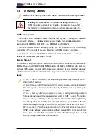
Note: Notch
should align
with the
receptive point
on the slot
Notch
Notch
Release
Tab
Release
Tab
DIMMII
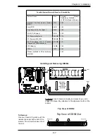
To Install:
Insert module vertically and press down until it
snaps into place. Pay attention to the alignment notch at the
bottom.
Installing and Removing DIMMs
To Remove:
Use your thumbs to gently push the
release tabs near both ends of the
module. This should release it from
the slot.
Top View of DDRII Slot
DDR2
Top View of DDR2
Possible System Memory Allocation & Availability
System Device
Size
Physical
Memory
Remaining (-Available)
(4 GB Total System Memory)
Firmware Hub flash memory (System
BIOS)
1 MB
3.99
Local APIC
4 KB
3.99
Area Reserved for the chipset
2 MB
3.99
I/O APIC (4 Kbytes)
4 KB
3.99
PCI Enumeration Area 1
256 MB
3.76
PCI Express (256 MB)
256 MB
3.51
PCI Enumeration Area 2 (if needed)
-Aligned on 256-MB boundary-
512 MB
3.01
VGA Memory
16 MB
2.85
TSEG
1 MB
2.84
Memory available to OS and other ap-
plications
2.84
Summary of Contents for C2SBM-Q
Page 1: ...C2SBM Q USER S MANUAL Revision 1 1a...
Page 52: ...3 6 C2SBM Q User s Manual Notes...
Page 78: ...4 26 C2SBM Q User s Manual Notes...
Page 84: ...A 6 C2SBM Q User s Manual Notes...
Page 90: ...B 6 C2SBM Q User s Manual Notes...

