Chapter 2: Installation
2-13
FA
N
1
JI2C2
JWOR
JFSB3
JF1
JWD
JLED
Battery
J40
DI
M
M
1A
DI
M
M
2A
DI
M
M
1B
I-SATA2
I-SATA3
SPEAKER
KB
/M
OU
SE
CPU Fan
J28
VG
A
JGS1
US
B
2/3
/4/
5
J43
J11
US
B 0
,1
J46
Au
dio
J41
4-Pin PWR
LGA 775 CPU
JFSB2
JFSB1
PC
I2
Slot5 PCI-E x4
JPAC
J9
Buzzer
SPKR
Slot4 PCI-33MHz
PC
I1
J1
2
J3
IDE#1
J4
5
FP USB 8/9
FP USB 6/7
J4
4
JL1
LE1
FP
CT
RL
Intel Q35
24
-pi
n A
TX
P
W
R
Audio CTRL
CD-IN
CD1
Front Audio
W
83
62
7D
HG
S
I/O
1
IDE CTRL
ITE 8213
J15
COM4
USB 10
JWOL
I-SATA0
I-SATA1
JS
4
JS
3
JS
1
JS
2
FA
N2
Fa
n3
JPUSB1
PC
I3
Slot7 PCI-E x16
JI2C1
JP2
Intel ICH9DO
JPUSB2
J4
7
JPL1
CO
M2
W
83
62
7D
HG
S
I/O
2
J14
COM3
Slot6 PCI-33MHz
PC
I1
JPT1
DI
M
M
2B
LAN CTRL
LA
N
1
C2
SB
M-
Q
CO
M1
J31
JBT1
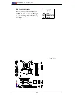
2-6 Connecting Cables
ATX/Auxiliary Power
Connectors
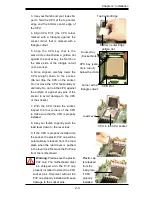
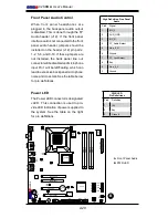
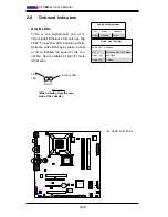
A 24-pin main power connector is
located at J40. This power connector
meet the SSI EPS 12V specification.
See the table on the right for pin
definitions.
ATX Power 24-pin Connector
Pin Definitions
Pin# Definition Pin # Definition
13
+3.3V
1
+3.3V
14
-12V
2
+3.3V
15
COM
3
COM
16
PS_ON
4
+5V
17
COM
5
COM
18
COM
6
+5V
19
COM
7
COM
20
Res (NC)
8
PWR_OK
21
+5V
9
5VSB
22
+5V
10
+12V
23
+5V
11
+12V
24
COM
12
+3.3V
12V 4-pin Power Con-
nector
Pin Definitions
Pins Definition
1 and 2
Ground
3 and 4
+12V
A.
24-pin ATX PWR
B.
4-pin PWR
A
B
4-pin CPU Power Connector
A 4-pin 12V power connector is located
at J41 on the motherboard. This power
connector also meets the SSI EPS
12V specification, and is required to
ensure adequate power to the proces-
sor. See the table on the right for pin
definitions.
Summary of Contents for C2SBM-Q
Page 1: ...C2SBM Q USER S MANUAL Revision 1 1a...
Page 52: ...3 6 C2SBM Q User s Manual Notes...
Page 78: ...4 26 C2SBM Q User s Manual Notes...
Page 84: ...A 6 C2SBM Q User s Manual Notes...
Page 90: ...B 6 C2SBM Q User s Manual Notes...

