background image

3-34


 AOC-LPZCR2 All-In-One Card User's Manual

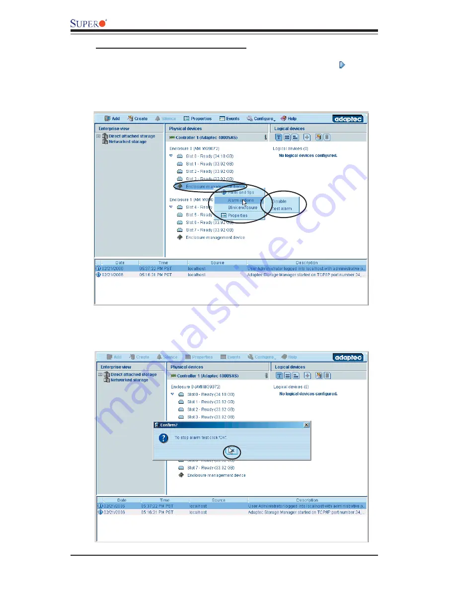
To Test the Alarm for an Enclosure

8. To check if SES-2 works properly, right-click on the triangle icon      to 

activate the pop-up menus as mentioned on the previous page. Then, you can 

right-click on Alarm actions to enable/disable the alarm or to test the alarm as 

shown below.

9. To stop the alarm testing, click OK when you are prompted to do so as 

shown in the following screen:

Summary of Contents for AOC-LPZCR2

Page 1: ...Rev 1 0 SUPER USER S GUIDE All In One ZCR Card AOC LPZCR2...

Page 2: ...HIS PRODUCT OR DOCUMENTATION EVEN IF ADVISED OF THE POSSIBILITY OF SUCH DAMAGES IN PARTICULAR THE VENDOR SHALL NOT HAVE LIABILITY FOR ANY HARDWARE SOFTWARE OR DATA STORED OR USED WITH THE PRODUCT INCL...

Page 3: ...delines 2 5 2 5 Installing the Controller Driver 2 6 2 5 1 Creating the Driver Floppy Disk 2 6 2 5 2 Adding the Driver into an Existing System 2 6 2 5 3 Installing the Driver into a New System 2 7 Cha...

Page 4: ...r SATA SAS SCSI only RAID 50 is available for SAS and SATA only 1 2 Introduction to SATA Serial ATA and SAS Serial Attached SCSI Serial ATA SATA is a physical storage interface It uses a single cable...

Page 5: ...MG9071 9072 Firmware Supports I2 C Interface Downward compatible with SATA disk drives Supports PCI X up to 100 MHz in the green slot See Note3 b SCSI based on the Q Logic GEM318 GEM359 Firmware Suppo...

Page 6: ...ZCR2 One Installation CD vi White Box with Correct Barcode Label showing AOC LPZCR2 1 6 An Important Note to the User The drawings and pictures shown in this manual were based on the latest PCB Revisi...

Page 7: ...e Netherlands Tel 31 0 73 6400390 Fax 31 0 73 6416525 Email sales supermicro nl General Information support supermicro nl Technical Support rma supermicro nl Customer Support Asia Paci c Address Super...

Page 8: ...AOC LPZCR2 User s Guide 1 8 Notes...

Page 9: ...er Locations Front view 5V LED DS14 I OProcessor AOC LPZCR2 7 0 2 5 DS13 3V LED Act J2 J6 I2 C J5 J3 SA TA2 J4 Cache Cache Cache Flash EPROM NVS RAM CPLD SCSI SAS J7 Buzzer Connector J1 Chapter 2 Tech...

Page 10: ...ription J2 Activity LED Connector J4 Buzzer Connector Connector Description J1 System Management Bus I2 C See I2 C cable connection on the next page J3 SCSI Mode On Enable J5 Serial ATA Mode SATA 2 Mo...

Page 11: ...e Pin2 Negtive Note Refer to the layout on Page 2 1 for the locations of the Connectors and LED Indicators SMB I2 C A System Management Bus header is located at J1 Connect the I2 C cable here to utili...

Page 12: ...d to monitor hot swap drives and inform the user of the status of these drives through LED indicators Refer to the table below for details on SAF TE LED Indicators See the Note below Note SAF TE in th...

Page 13: ...gold contacts When handling chips or modules avoid touching their pins Put the card and peripherals back into their antistatic bags when not in use General Safety Guidelines Always disconnect power c...

Page 14: ...ystem already installed and the AOC LPZCR2 driver is being installed as a Secondary Controller For the Windows Operating System a Install the controller and make sure that its BIOS appears in POST b S...

Page 15: ...fy that the driver is included in an additional device the oppy disk and press Enter Refer to Page 2 6 e When the Adaptec s driver disk Adaptec RAID Controller is located press Enter f Press Enter aga...

Page 16: ...AOC LPZCR2 User s Guide 2 8 Notes...

Page 17: ...micro bootable CDs that came with your card Note For the Adaptec RAID Con guration Utility to function properly you will need to correctly setup the jumper settings of your add on card rst before usin...

Page 18: ...gs for disk drives 3 Disk Utility this utility allows the user to format and verify disk drives To Use the Adaptec RAID Con guration Utility Note the con guration procedures listed below are applicabl...

Page 19: ...ration Utility allows you to create manage delete arrays and specify hot spare disk drives 1 Select Array Con guration Utility from the RAID Con guration Main Menu Figure 3 1 on Page 3 3 and press Ent...

Page 20: ...nt Please refer to the section Initializing Disk Drives for disk initialization 1 Turn on your computer When prompted press Ctrl and A to access the Adaptec RAID Utility 2 From the RAID Con guration M...

Page 21: ...pe you can select Volume RAID 0 RAID 1 RAID 5 RAID 10 or RAID 50 Please refer to the table below for the minimum of hard drives required for each RAID setting Select Volume to con gure a disk drive as...

Page 22: ...e RAID via to select the different methods under RAID 0 RAID 1 RAID 5 RAID 10 and RAID 50 11 Press Esc to return to the previous menu Note Once the array is created and its properties are assigned you...

Page 23: ...ays will display on the right Select the array you want to view as shown below 5 Press Enter and the Array Properties dialogue box will display showing detailed information The physical disks associat...

Page 24: ...l erase all data from the Array Do you want to continue Yes No Note you cannot delete arrays that have valid partitions You need to remove partitions before deleting an array 4 Press Yes to delete the...

Page 25: ...hlight and select the array you want to make as the rst bootable and press Ctrl and B simul taneously 3 The array selected as the 1st bootable array will appear on the top the rst of the List 4 To re...

Page 26: ...rray you wish to con gure as a hot spare and press Ctrl and S simultaneously 3 A Hotspares dialogue box displays showing the drives that can be con g ured as Hotspares 4 Select the drive you wish to c...

Page 27: ...y you wish to delete and press Ctrl and S simultaneously 3 The Hotspares dialogue box displays showing the drives that have been con gured as Hotspares 4 From the Assigned Hotspare List select the dri...

Page 28: ...the disk drive in an array Do not initialize a disk that is part of a boot array since disk initialization will overwrite the data stored inside the disk Refer to the item Viewing Array Prop erties t...

Page 29: ...enu select Initialize Drives as shown above and press Enter The following screen will display 4 From the list of drives on the left select the disk drive you wish to initialize and press Insert The dr...

Page 30: ...to initialize When all the drives to be initialized are selected press Enter and a warning message will display as shown below 6 Make sure that you have selected the correct disk drives to initialize...

Page 31: ...or more information To Rebuild an array 1 From the Main Menu select Manage Arrays From the list of arrays select the array you want to rebuild 2 Press Ctrl and R simultaneously to rebuild an array To...

Page 32: ...our system When prompted press Ctrl and A simultane ously to access the Array Con guration Utility 2 When the Array Con guration Utility Main Menu appears select Array Con guration Utility and press E...

Page 33: ...e then press Enter 6 The following message displays Warning Secure Erase will erase all informa tion from the selected drive Do you really want to continue Press Y to erase the drive Press N to abort...

Page 34: ...on Menu select SCSISelect Utility and press Enter as shown below Using the Controller Con guration Utility 3 To con gure the RAID Controller or view Controller settings select Controller Con guration...

Page 35: ...he selected channel displays as shown on the next page Using the SCSI Con guration Utility 1 From the Array Con guration Utility Main Menu select SCSISelect Utility and press Enter 2 From the SCSISele...

Page 36: ...ptions and press Enter The current settings of the selected drive will be displayed as shown on the next page 4 To con gure an item use the arrow keys to select the item and press Enter A dialogue box...

Page 37: ...the setting of an item use the arrow keys to select the item and press Enter in the menu as shown above Please refer to the table below for detailed information 8 To restore the default setting press...

Page 38: ...press Enter A dialogue box will appear 5 Select the desired setting in the dialogue box and press Enter to select the option 6 Press F6 to restore the default setting Press Esc to return to the previ...

Page 39: ...erialSelect Utility Please refer to Section 3 2 1 for SCSI and Section 3 2 3 for SAS Utility Con guration settings To Use the SerialSelect Utility 1 Turn on your computer When prompted press Ctrl and...

Page 40: ...lity to Con gure SAS Settings 1 Turn on your computer When prompted press Ctrl and A to access the Adaptec RAID Con guration Utility 2 From the RAID Con guration Main Menu Figure 3 1 on Page 3 3 selec...

Page 41: ...ccess the Physical Con guration submenu as shown below 2 Select Physical Con guration and press Enter to access SAS SATA Device Con guration submenu 3 Use the arrow keys to select an item Press Enter...

Page 42: ...Disk Utilities for SCSI only Note Please refer to Page 3 1 for SCSI Jumper con guration before using Disk Utilities Please refer to Section 3 3 2 for SAS and SATA Disk Utilities 1 Power on your comput...

Page 43: ...n 3 27 3 Once the disk drive is selected press Enter The Adaptec RAID Utility starts re scanning the selected drive and a screen will display as below Note Please refer to the following section for SA...

Page 44: ...tion Main Menu select Disk Utilities and press Enter After disk scan the following screen displays 2 When a dialogue box as shown above displays prompting you to make a selection select the disk you w...

Page 45: ...isk Media from the displayed dialogue box and press Enter 4 A dialogue box appears showing you the status of the disk drive and warn ing you that the disk drive selected will be scanned for media defe...

Page 46: ...Adaptec ASM version you have is compatible with your version of the SES 2 Driver 6 Make sure that you have the Administrator s privileges and a password is pre keyed in the system for you already Whe...

Page 47: ...d for experienced users only 3 Customized RAID Use this option to customize your own RAID setting The default setting is Internal RAID The default setting for Special is External RAID Using the ASM Ut...

Page 48: ...in the Pass word eld enter the password that has been pre set for you Note you will need to have the Administrator privileges and a password that has already been set in the ASM for you to log in 5 A...

Page 49: ...mware is used two enclosures with eight HDDs will be displayed If the AMI MG 9071 is used only one enclosure with 4 HDDs will be available 2 If the triangle icon appears the Enclosure Management Devic...

Page 50: ...operly right click on the triangle icon to activate the pop up menus as mentioned on the previous page Then you can right click on Alarm actions to enable disable the alarm or to test the alarm as sho...

Page 51: ...page 11 To stop the LED blinking test simply click OK when prompted to do so as shown below To Display the Property for an Enclosure 12 You can also display the property for the enclosure by right cl...

Page 52: ...gle icon to display the hard drives included in the enclosure as shown below To Create a Hot Spare Drive 2 Right click on a device that you wish to create as a Hot Spare Drive to acti vate the pop up...

Page 53: ...Single Volume 2 Right click on a device that you wish to create as a Single Volume to activate the pop up menu as shown in the second picture on Page 3 36 3 From the pop up menu as shown select Creat...

Page 54: ...pop up menu as shown in the second picture on Page 3 36 3 From the pop up menu select Clear and hit Enter 4 A warning message will appear Click OK if you want to clear arrays Click cancel if you are n...

Page 55: ...l to cancel the procedure Note It is a lengthy process to verify the status of a device To Verify Fix an Array 2 Right click on a device that you wish to verify and rebuild the array to activate the p...

Page 56: ...h the procedure Click cancel to cancel the procedure Warning Secure Erasing is a long time consuming process It depends on the HDD size To Initialize a Drive 2 Right click on a device that you wish to...

Page 57: ...Right click on the triangle to activate the pop up menu Select Managed Sys tem or Management Station and hit Enter as shown below For a desktop user select Managed System 3 Type in the elds Host name...

Page 58: ...10 and RAID 50 for disk drives 1 Double click on the second icon Create on the tool bar and hit Enter as shown above The following screen will appear You can select Express con guration to use manufa...

Page 59: ...previous page The following screen appears Note ASM will select the best con guration for your storage setup In the following case RAID 5 is chosen To Con gure a Default RAID Setting as assigned by th...

Page 60: ...To change the default RAID con guration to another setting double click Modify logical devices as shown above and the following screen will appear 4 Click on the RAID setting of your choice to select...

Page 61: ...uration 3 45 5 Follow the instructions given on the screen and click Next until you complete the RAID con guration An example is shown below 6 You can click Back to return to the previous screen as sh...

Page 62: ...selected a RAID con guration and would like to cancel the opera tion you can click Remove logical device and then click Next on the screen as shown above to cancel the con guration selection To Exit...

Page 63: ...lick the Crossed out HDD icon on the tool bar and hit Enter as shown above The following screen will ap pear 2 A warning message appears indicating that you will lose all data stored in the original d...

Page 64: ...AOC LPZCR2 All In One Card User s Manual 3 Once an array is deleted the following screen appears Note When the grayed out HDD icon appears it indicated that there are no more logical devices to be del...

Page 65: ...ed in the PCI green slot Check if the motherboard s BIOS is updated You can download a updated BIOS from our web site at www supermicro com 2 Problem I cannot see the card in the operating system Reco...

Page 66: ...back panel and the controller Also make sure that the hard drives are properly seated in the drive bay If possible swap the drives around to determine if the drive connections or the controller is ba...

Reviews: