background image

7-4

S

UPER

S

TORAGE

S

YSTEM 6047R-E1R36L User's Manual

7-3   Advanced Setup Confi gurations

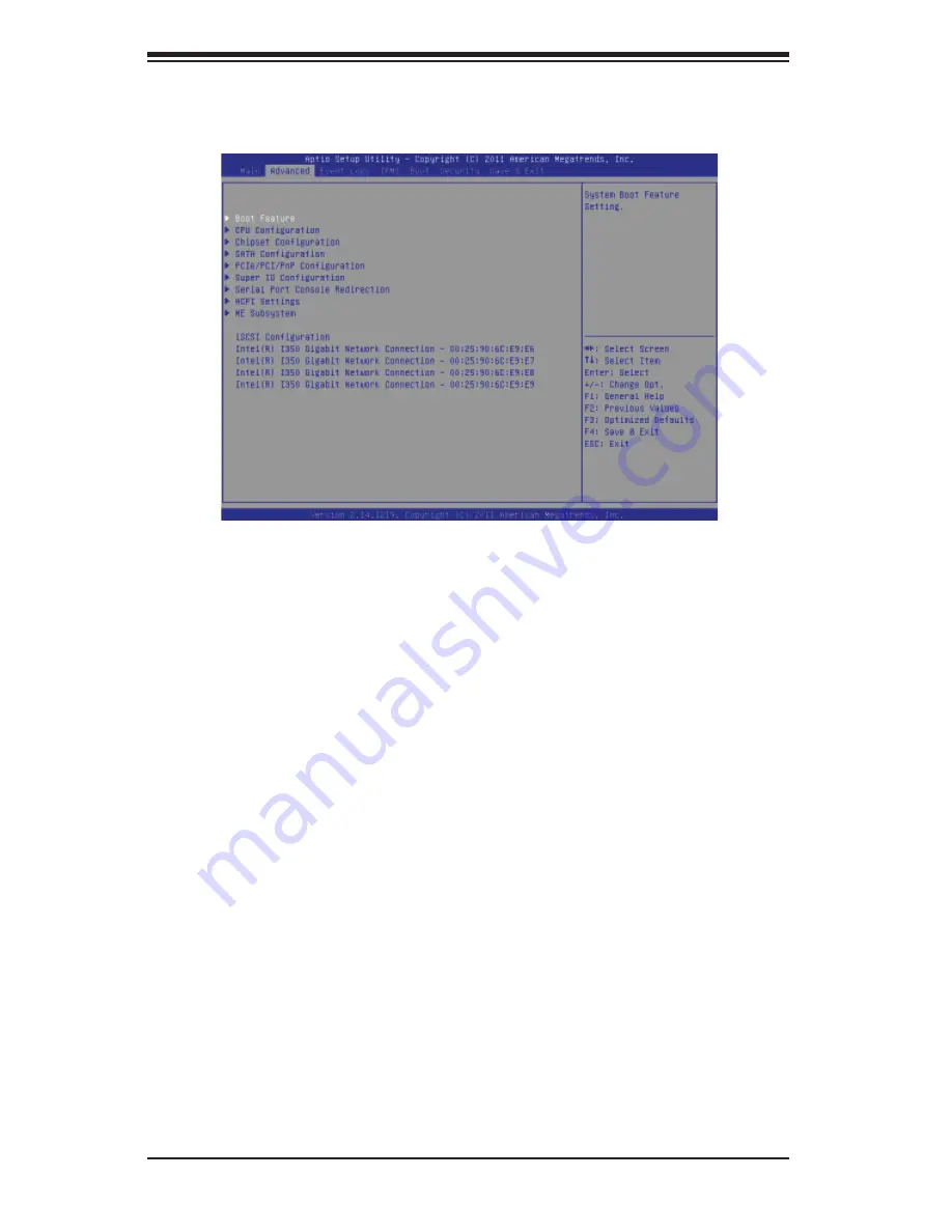
Select the Advanced tab to access the following submenu items. 

X

Boot Feature

Quiet Boot

This feature allows the user to select bootup screen display between POST mes-
sages and the OEM logo. Select Disabled to display the POST messages. Select 
Enabled to display the OEM logo instead of the normal POST messages. The op-
tions are 

Enabled

 and Disabled. 

AddOn ROM Display Mode

Use this item to set the display mode for the Option ROM. Select Keep Current to 
use the current AddOn ROM Display setting. Select Force BIOS to use the Option 
ROM display mode set by the system BIOS. The options are Keep Current and  

Force BIOS

Bootup Num-Lock

Use this feature to set the Power-on state for the Numlock key. The options are 
Off and 

On

.

Wait For 'F1' If Error

Select Enabled to force the system to wait until the 'F1' key is pressed if an error 
occurs. The options are Disabled and 

Enabled

.

Interrupt 19 Capture

Interrupt 19 is the software interrupt that handles the boot disk function. When this 
item is set to Enabled, the ROM BIOS of the host adaptors will "capture" Interrupt 19 

Summary of Contents for 6047R-E1R36L

Page 1: ...SUPER STORAGE SYSTEM 6047R E1R36L SUPER USER S MANUAL 1 0...

Page 2: ...any such disputes Super Micro s total liability for all claims will not exceed the price paid for the hardware product FCC Statement This equipment has been tested and found to comply with the limits...

Page 3: ...D JBOD serverboard and the SC847E16 R1K28LPB chassis Chapter 2 Server Installation This chapter describes the steps necessary to install the 6047R E1R36L into a rack and check out the server configura...

Page 4: ...configuring the serverboard Chapter 6 Advanced Chassis Setup Refer to Chapter 6 for detailed information on the SC847E16 R1K28LPB chassis You should follow the procedures given in this chapter when in...

Page 5: ...Notes Preface v...

Page 6: ...e System 2 1 2 3 Preparing for Setup 2 1 Choosing a Setup Location 2 1 Rack Precautions 2 2 Server Precautions 2 2 Rack Mounting Considerations 2 3 Ambient Operating Temperature 2 3 Reduced Airflow 2...

Page 7: ...rd 5 1 Precautions 5 1 Unpacking 5 2 5 2 Connecting Cables 5 2 Connecting Data Cables 5 2 Connecting Power Cables 5 2 Connecting the Control Panel 5 2 5 3 Rear I O Ports 5 3 5 4 Installing the Process...

Page 8: ...6 6 Hard Drive Backplane 6 7 Removing the Air Shroud 6 8 6 6 Installing Optional Fixed Hard Drives 6 9 6 7 Power Supply 6 10 Power Supply Failure 6 10 6 7 Attaching a JBOD Expansion Chassis 6 11 Chap...

Page 9: ...icro com In addition to the serverboard and chassis various hardware components have been included with the 6047R E1R36L as listed below Two passive CPU heatsinks SNK P0048P Three 8 cm system fans FAN...

Page 10: ...DIMM or up to 128 GB of ECC non ECC DDR3 Unbuffered memory UDIMM See Chapter 5 for details SAS A SAS 2 0 controller is integrated into the serverboard providing 8x lanes of 6Gb s SAS with basic HBA IT...

Page 11: ...24 on the front of the chassis and 12 located on the rear of the chassis which are hot swappable units Front Control Panel The control panel on the SuperServer 6047R E1R36L provides you with system m...

Page 12: ...3 0 x8 PCIE 3 0 x4 SAS LSI LAN1 LAN2 RJ45 RJ45 LAN3 LAN4 VGA CONN IPMI LAN PHY RTL8201F RJ45 RJ45 SAS2308 Powerville I350 AM4 Quad GLAN J26 SLOT 6 L SAS0 3 L SAS4 7 J21 SLOT 1 PCIE 3 0 x8 DDR3 DIMM H...

Page 13: ...D3 LEDM1 LED2 LAN2 4 LAN1 3 CPU1 CPU2 CPU2 CPU1 CPU2 CPU1 PWR I2C UID P2 DIMME1 P2 DIMMF2 P2 DIMMF1 P2 DIMMG2 P2 DIMMG1 P2 DIMMH2 P2 DIMMH1 P1 DIMMA2 P1 DIMMA1 P1 DIMMB2 P1 DIMMB1 P1 DIMMC1 P1 DIMMC2...

Page 14: ...Address Super Micro Computer B V Het Sterrenbeeld 28 5215 ML s Hertogenbosch The Netherlands Tel 31 0 73 6400390 Fax 31 0 73 6416525 Email sales supermicro nl General Information support supermicro n...

Page 15: ...Server 6047R E1R36L It should be situated in a clean dust free area that is well ventilated Avoid areas where heat electrical noise and electromagnetic fields are generated You will also need it place...

Page 16: ...omponent from the rack You should extend only one component at a time extending two or more si multaneously may cause the rack to become unstable Server Precautions Review the electrical and general s...

Page 17: ...omised Mechanical Loading Equipment should be mounted into a rack so that a hazardous condition does not arise due to uneven mechanical loading Circuit Overloading Consideration should be given to the...

Page 18: ...sembly procedure will differ slightly You should also refer to the installation instructions that came with the rack unit you are using Note This rail will fit a rack between 27 and 34 45 deep Identif...

Page 19: ...ls on the side of the chassis aligning the hooks of the chas sis with the inner rail holes Make sure that the rail faces outward so that it will fit with the rack s mounting bracket 2 Slide the rail t...

Page 20: ...me direction 2 Adjust both the short and long brackets to the proper distance so that the rail fits snugly into the rack 3 Secure the long bracket to the front side of the outer rail with two M5 screw...

Page 21: ...Chapter 2 Server Installation 2 7 Figure 2 4 Installing the Outer Rails to the Server Rack 1 3 1 3 1 2...

Page 22: ...assis rails A with the front of the rack rails B 3 Slide the chassis rails into the rack rails keeping the pressure even on both sides you may have to depress the locking tabs when inserting When the...

Page 23: ...t button and a power on off button Reset Use the reset button to reboot the system Power This is the main power button which is used to apply or turn off the main system power Turning off system power...

Page 24: ...re When on continuously it indicates an overheat condition which may be caused by cables obstructing the airflow in the system or the ambient room temperature being too warm Check the routing of the c...

Page 25: ...ing 3 4 Drive Carrier LEDs Each drive carrier has two LEDs Green When illuminated the green LED on the front of the drive carrier indi cates drive activity A connection to the backplane enables this L...

Page 26: ...3 4 SUPERSTORAGESYSTEM 6047R E1R36L User s Manual Notes...

Page 27: ...power you should first power down the system with the operating system first and then unplug the power cords of all the power supply units in the system When working around exposed electrical circuits...

Page 28: ...your body which are excellent metal conductors that can create short circuits and harm you if they come into contact with printed circuit boards or areas where power is present Serverboard Battery CAU...

Page 29: ...use Touch a grounded metal object before removing the board from the antistatic bag Do not let components or PCBs come into contact with your clothing which may retain a charge even if you are wearing...

Page 30: ...his practice is not strictly followed Figure 4 1 Installing the Onboard Battery L T UM ATTERY ATTERY OL ER Please handle used batteries carefully Do not damage the battery in any way a damaged battery...

Page 31: ...ully see previous chapter To prevent the serverboard from bending keep one hand under the center of the board to support it when handling The following measures are generally sufficient to protect you...

Page 32: ...ir locations noted should be connected See the layout on page 5 10 for connector locations Control Panel cable JF1 USB cable for front side access USB4 5 Important Make sure the the cables do not come...

Page 33: ...I O Ports NMI x Key 3 3V ID UID SW 3 3V Stby NIC1 Activity LED NIC2 Activity LED Red Blue Cathode 3 3V Reset Button Power Button Ground x Key Power On LED HDD LED NIC1 Link LED NIC2 Link LED OH Fan F...

Page 34: ...ing any hardware components Make sure that you install the processor into the CPU socket before you install the CPU heatsink If you buy a CPU separately make sure that you use an Intel certified multi...

Page 35: ...ARNING plastic cap from the socket 5 Use your thumb and index finger to hold the CPU by its edges Align the CPU keys which are semi circle cutouts against the socket keys 6 Once they are aligned caref...

Page 36: ...te again and double check that the CPU is aligned properly 7 With the CPU in the socket in spect the four corners of the CPU to make sure that they are flush with the socket 8 Close the load plate Loc...

Page 37: ...eatsink on top of the CPU so that the four mounting holes are aligned with those on the Serverboard s and the Heatsink Bracket underneath 3 Screw in two diagonal screws i e the 1 and the 2 screws unti...

Page 38: ...erverboard in the sequence as shown in the illustration below 2 Gently wriggle the heatsink to loosen it from the CPU Do not use excessive force when wriggling the heatsink 3 Once the heatsink is loos...

Page 39: ...attention to the notch along the bottom of the module to avoid installing incorrectly see Figure 5 3 3 Use your thumbs to gently press down on both ends of the DIMM module until it snaps into place in...

Page 40: ...MMG1 P2 DIMMH1 2 CPUs 10 16 DIMMs CPU1 CPU2 P1 DIMMA1 P1 DIMMB1 P1 DIMMC1 P1 DIMMD1 P2 DIMME1 P2 DIMMF1 P2 DIMMG1 P2 DIMMH1 Any memory pairs in P1 P2 DIMM slots 2 CPUs 16 DIMMs CPU1 CPU2 P1 DIMMA1 P1...

Page 41: ...detailed information on memory support and updates please refer to the SMC Recommended Memory List posted on our website at http www supermicro com support resources mem cfm Intel E5 2600 Series Proc...

Page 42: ...5 12 SUPERSTORAGESYSTEM 6047R E1R36L User s Manual 1 CPU 2 DIMMs 1 CPU 5 8 DIMMs 1 CPU 4 DIMMs Populate blue DIMM slots first then the rest in any order...

Page 43: ...nced Serverboard Setup 5 13 2 CPU 6 DIMMs 2 CPU 8 DIMMs 2 CPU 10 16 DIMMs For two CPUs and 16 DIMMs populate all DIMM slots Populate blue DIMM slots first then any memory pairs in the remaining slots...

Page 44: ...by removing the shield for the PCI slot you wish to populate 2 Fully seat the card into the slot pushing down with your thumbs evenly on both sides of the card 3 Finish by using a screw to secure the...

Page 45: ...RM_I2C2 JVR1 FAN5 FAN6 FAN8 FAN7 FAN1 FAN2 FAN3 FAN4 JF2 T SGPIO1 T SGPIO2 JUSB6 JSD1 JBT1 JBAT1 JTPM1 JF1 JPI2C1 JOH1 JI2C2 JL1 JSTBY1 JUIDB J4 JD1 LED3 LEDM1 LED2 LAN2 4 LAN1 3 CPU1 CPU2 CPU2 CPU1 C...

Page 46: ...JD1 Speaker Power LED Indicator JF1 Front Panel Control Header JF2 LAN3 NIC3 LAN4 NIC4 LED Headers JIPMB1 4 pin External BMC I2 C Header for an IPMI Card JPI2 C1 System Management SMBbus I2 C Header...

Page 47: ...nector Warning on Pg 1 6 JPW2 3 12V 8 Pin Power Connectors See Warning on Pg 1 6 JPW4 12V 4 Pin Power Connectors See Warning on Pg 1 6 JSD1 SATA DOM Device on Module Power Connector JSTBY1 5V Standby...

Page 48: ...22 5V 10 12V 23 5V 11 12V 24 COM 12 3 3V Reset Button Pin Definitions JF1 Pin Definition 3 Reset 4 Ground Power Button Pin Definitions JF1 Pin Definition 1 Power Signal 2 Ground Secondary Power Conne...

Page 49: ...ons JF1 Pin Definition 7 Vcc 8 Ground NIC2 LED Pin Definitions JF1 Pin Definition 9 Vcc 10 Ground HDD LED Pin Definitions JF1 Pin Definition 13 Vcc 14 HD Active NIC2 JLAN2 LED The LED connections for...

Page 50: ...table on the right for pin definitions NMI Button Pin Definitions JF1 Pin Definition 19 Control 20 Ground Fan Header Pin Definitions FAN1 8 Pin Definition 1 Ground Black 2 12V Red 3 Tachometer 4 PWR...

Page 51: ...n be used to provide audible indica tions for various beep codes See the table on the right for pin definitions Internal Buzzer SP1 Pin Definition Pin Definitions Pin 1 Pos Beep In Pin 2 Neg Alarm Spe...

Page 52: ...the table on the right for pin definitions SGPIO Header Pin Definitions Pin Definition Pin Definition 1 NC 2 NC 3 Ground 4 DATA Out 5 Load 6 Ground 7 Clock 8 NC NC No Connection Back Panel USB USB 0...

Page 53: ...4 Ground 5 3 3V Standby Power Header The 5V Standby Power header is located at JSTBY1 on the mother board See the table on the right for pin definitions You must also have a card with a Standby Power...

Page 54: ...4 ports on the backplane The Rear UID LED LE2 is located next to the UID switch The control panel UID LED connection is on pins 7 8 of JF1 Connect a cable to pin 8 on JF1 for Front Panel UID LED indic...

Page 55: ...used to clear CMOS which will also clear any passwords Instead of pins this jumper consists of contact pads to prevent accidentally clearing the contents of CMOS To clear CMOS 1 First power down the...

Page 56: ...ts on the serverboard See the table on the right for jumper settings GLAN Enable Jumper Settings Jumper Setting Definition 1 2 Enabled default 2 3 Disabled Watch Dog Enable Disable Watch Dog is a syst...

Page 57: ...g any components See the table on the right for more details IPMI Dedicated LAN LEDs An additional IPMI Dedicated LAN is also located on the I O backplane The amber LED on the right indicates activity...

Page 58: ...HostRAID User s Guide posted on our website http www supermicro com Serial ATA Ports There are six Serial ATA Ports I SATA0 I SATA 5 located on the serverboard including four SATA2 ports and two SATA...

Page 59: ...ed with your serverboard Driver Tool Installation Display Screen Note Click the icons showing a hand writing on paper to view the readme files for each item Click the computer icons to the right of th...

Page 60: ...vironment and operations of your system SuperDoctor III displays crucial system information such as CPU temperature system voltages and fan status See the Figure below for a display of the SuperDoctor...

Page 61: ...Interface Display Screen Remote Control Note The SuperDoctor III program and User s Manual can be downloaded from the Supermicro web site at http www supermicro com products accessories software Supe...

Page 62: ...5 32 SUPERSTORAGESYSTEM 6047R E1R36L User s Manual Notes...

Page 63: ...em very carefully The following measures are generally sufficient to protect your equipment from ESD damage Precautions Use a grounded wrist strap designed to prevent static discharge Touch a grounded...

Page 64: ...ed these wires together to simplify the connection Connect the cable from JF1 on the serverboard to the Control Panel PCB printed circuit board Make sure the red wire plugs into pin 1 on both connecto...

Page 65: ...riods of time do NOT operate the server without the cover in place The chassis cover must be in place to allow proper airflow and prevent overheating 1 2 1 2 1 2 1 2 1 3 Removing the Chassis Cover 1 U...

Page 66: ...ed fan Remove the top chassis cover while the system is still running to determine which of the fans has failed Replacing System Fans Removing a Fan 1 Remove the top chassis cover while the system is...

Page 67: ...remove power to replace or swap SATA drives Proceed to the next step for instructions Note You must use standard 1 high drives in the SuperServer 6047R E1R36L DVD ROM Floppy Disk Drive For installing...

Page 68: ...drive carrier straight out Installing a Hard Drive to the Hard Drive Tray 1 Remove the two screws securing the dummy drive to the drive tray and remove the dummy drive Place the hard drive tray on a...

Page 69: ...es plug into a backplane that provides power drive ID and bus termi nation A RAID controller can be used with the backplane to provide data security The operating system you use must have RAID support...

Page 70: ...place when the system is operating please follow this procedure Air shrouds concentrate airflow to maximize fan efficiency The SC846 chassis air shroud does not require screws to set up Installing th...

Page 71: ...ur round washers and four screws with the holes in the hard drive and the holes in the bracket 2 Secure the hard drive to the bracket using the screws and washers provided 3 See the instructions below...

Page 72: ...e and remain on until the failed module has been replaced Replacements can be ordered directly from Supermicro see contact information in the Preface The power supply modules have a hot swap capabilit...

Page 73: ...OD Expansion Chassis The SSG 6047R E1R36L features dual JBOD expansion ports The figure below illustrates the recommended expansion strategy The JBOD attachment will vary depending on the specific JBO...

Page 74: ...12 SUPERSTORAGESYSTEM 6047R E1R36L User s Manual Figure 6 8 JBOD Expansion Port JBOD OUT downstream ports JBOD OUT downstream port JBOD OUT downstream port JBOD IN upstream port JBOD IN upstream port...

Page 75: ...the options that can be configured Grayed out options cannot be configured Options in blue can be configured by the user The right frame displays the key legend Above the key legend is an area reserve...

Page 76: ...tility From the main menu you can access the other setup screens An AMI BIOS identification string is displayed at the left bottom corner of the screen below the copyright message Warning Do not upgra...

Page 77: ...key to move between fields The date must be entered in Day MM DD YY format The time is entered in HH MM SS format Note The time is in the 24 hour format For example 5 30 P M appears as 17 30 00 Super...

Page 78: ...set the display mode for the Option ROM Select Keep Current to use the current AddOn ROM Display setting Select Force BIOS to use the Option ROM display mode set by the system BIOS The options are Ke...

Page 79: ...s feature is set to 4 Seconds Override the system will power off when the user presses the power button for 4 seconds or longer The options are Instant Off and 4 Seconds Override Restore on AC Power L...

Page 80: ...nts whenever needed The options are Disabled and Enabled RTID Record Types IDs This feature displays the total number of Record Type IDs for local and remote pools The options are Optimal and Alternat...

Page 81: ...feature is set to Disabled The CPU prefetches the cache line for 64 bytes If this feature is set to Enabled the CPU fetches both cache lines for 128 bytes as comprised The options are Disabled and Ena...

Page 82: ...Available when Power Technology is set to Custom Select Enabled to use the Turbo Mode to boost system performance The options are Enabled and Disabled C1E Support Available when Power Technology is se...

Page 83: ...n Power Limit This item displays the power limit in watts set by the user during which long duration power is maintained The default setting is 0 Factory Long Duration Maintained This item displays th...

Page 84: ...stem resource for other tasks The options are Disabled and Enabled DCA Support When set to Enabled this feature uses Intel s DCA Direct Cache Access Technology to improve data transfer efficiency The...

Page 85: ...ns are Enabled and Disabled QPI Quick Path Interconnect Link Speed Mode Use this feature to select data transfer speed for QPI Link connections The options are Slow and Fast QPI Link Frequency Select...

Page 86: ...n the specification The options are Force DDR3 800 Force DDR3 1066 Force DDR3 1333 Force DDR3 1600 and Force SPD and Auto Channel Interleaving This feature selects from the different channel interleav...

Page 87: ...for the Intel PCH chip PCH Information This feature displays the following PCH information Name This item displays the name of the PCH chip Stepping This item displays the status of the PCH stepping U...

Page 88: ...ATA port as detected by the BIOS SATA Mode Use this feature to configure SATA mode for a selected SATA port The options are Disabled IDE Mode AHCI Mode and RAID Mode The following are displayed depend...

Page 89: ...nabled to enable hot plug support for the particular port The options are Enabled and Disabled XPCIe PCI PnP Configuration PCI ROM Priority Use this feature to select the Option ROM to boot the system...

Page 90: ...support The options are Disabled Force L0s and Auto Warning Enabling ASPM support may cause some PCI E devices to fail CPU1 Slot 1 PCI E 3 0 x8 OPROM CPU1 Slot 2 PCI E 3 0 x8 OPROM CPU2 Slot 3 PCI E...

Page 91: ...item displays the settings of Serial Port 1 Change Settings This option specifies the base I O port address and the Interrupt Request address of Serial Port 1 Select Disabled to prevent the serial por...

Page 92: ...re the following Console Redirection settings for a COM Port specified by the user Console Redirection Select Enabled to use a COM Port selected by the user for Console Redirection The options are Ena...

Page 93: ...end of a serial data packet Select 1 Stop Bit for standard serial data communication Select 2 Stop Bits if slower devices are used The options are 1 and 2 Flow Control This feature allows the user to...

Page 94: ...ate with a remote server The options are COM1 and COM2 SOL Terminal Type This feature allows the user to select the target terminal emulation type for Con sole Redirection Select VT100 to use the ASCI...

Page 95: ...ess ACPI support The options are Enabled and Disabled High Precision Event Timer Select Enabled to activate the High Precision Event Timer HPET that produces periodic interrupts at a much higher frequ...

Page 96: ...ly ac tive or deactivated TPM Owner Status This item displays the status of TPM Ownership XIntel TXT LT SX Configuration Intel TXT LT SX Hardware Support This feature indicates if the following hardwa...

Page 97: ...use IQN format The following actions can also be performed Add an Attempt Delete Attempts Commit Discard Changes and Exit Change Attempt Order Commit Discard Changes and Exit Intel Ethernet Controller...

Page 98: ...fy the duration for LEDs to blink The range is from 0 15 seconds The default setting is 0 PORT CONFIGURATION INFORMATION This section displays the following port information UEFI Driver Adapter PBA Ch...

Page 99: ...tem Management BIOS Event Logging during system boot The options are Enabled and Disabled Runtime Error Logging Support Select Enabled to support Runtime Error Logging The options are Enabled and Disa...

Page 100: ...othing and Erase Immediately SMBIOS Event Log Standard Settings Log System Boot Event Select Enabled to log system boot events The options are Disabled and Enabled MECI Multiple Event Count Increment...

Page 101: ...stalled in your system XSystem Event Log Enabling Disabling Options SEL Components Select Enabled for all system event logging at bootup The options are Enabled and Disabled Erasing Settings Erase SEL...

Page 102: ...ake effect when the system is rebooted The options are No and Yes Configuration Address Source This feature allows the user to select the source of the IP address for this computer If Static is select...

Page 103: ...ystem Boot Option Priorities Boot Option 1 Boot Option 2 Boot Option 3 etc Use this feature to specify the sequence of boot device priority Network Devices Hard Disk Drives Use these options to set th...

Page 104: ...when a password entry is required Select Setup to require the password only when entering setup Select Always to require the pass word when entering setup and on each boot The options are Setup and Al...

Page 105: ...Reset When you have completed the system configuration changes select this option to save the changes and reboot the computer so that the new system configuration settings can take effect Select Save...

Page 106: ...Defaults Select this feature and press Enter to save the current settings as the user s defaults When the dialog box appears asking you if you want to save values as user s defaults select Yes to sav...

Page 107: ...system manufacturer for possible repairs These fatal errors are usually communicated through a series of audible beeps The numbers on the fatal error list correspond to the number of beeps for the cor...

Page 108: ...A 2 SUPERSTORAGESYSTEM 6047R E1R36L User s Manual Notes...

Page 109: ...up to 512 GB of registered ECC DDR3 1333 1066 800 Registered memory RDIMM or up to 128 GB of ECC non ECC DDR3 Unbuffered memory UDIMM Note see Section 5 6 for details Drive Bays Thirty six hot swap dr...

Page 110: ...280W Part PWS 1K28P SQ Rated Output Voltages 1000W 12V 83A 5Vsb 4A 1280W 12V 106 7A 5Vsb 4A System Input Requirements AC Input Voltage 100 240V AC auto range Rated Input Current 1000W output 100 140V...

Page 111: ...1000 4 4 EN 61000 4 5 EN 61000 4 6 EN 61000 4 8 EN 61000 4 11 Safety CSA EN IEC UL 60950 1 Compliant UL or CSA Listed USA and Canada CE Marking Europe California Best Management Practices Regulations...

Page 112: ...to perform be reasonably expected to result in significant injury or loss of life or catastrophic property damage Accordingly Supermicro dis claims any and all liability and should buyer use or sell s...

Reviews: