Chapter 6: Advanced Chassis Setup
6-17
F424AG-R2K04BP
Front of Node
Rear of Node
Two low-profi le expansion cards
Two 3.5" HDDs
Two optional fi xed fans
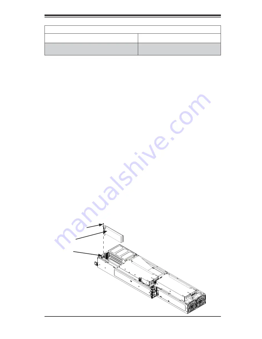
Installing a Low-Profi le Expansion Card
Each serverboard node supports two low-profi le expansion cards.
Installing an Expansion Card into a Node
1. Remove the power cord from the rear of the node as described in Section
6-3. Remove the node from the chassis as described in Section 6-4. Place
the node on a fl at, stable surface and remove the node cover as described in
Section 6-7.
2. Remove the mounting screw which secures the PCI-E slot cover in the PCI-E
slot and set this aside for later use.
3. Remove the PCI-E slot cover by sliding it upward and out of the PCI-E slot.
4. Simultaneously slide the expansion card into the open PCI-E slot, while
inserting the expansion card into the serverboard.
5. Secure the expansion card to the node using the screws that were previously
set aside.
6. Replace the air shroud as described in the following section.
7. Place the cover on the node and secure it with the screws previously set
aside.
8. Return the node to its bay in the chassis.
Figure 6-17: Installing the Expansion Card
PCI-E Slot
Expansion
Card
Mounting Screw
Summary of Contents for FatTwin F628G3-FT+
Page 1: ...FatTwin F628G3 FT F628G3 FTPT USER S MANUAL Revision 1 0...
Page 5: ...v FatTwin F628G3 FT FTPT User s Manual Notes...
Page 10: ...x Notes FatTwin F628G3 FT FTPT User s Manual...
Page 20: ...1 10 FatTwin F628G3 FT FTPT User s Manual Notes...
Page 30: ...2 10 FatTwin F628G3 FT FTPT User s Manual Notes...
Page 34: ...FatTwin F628G3 FT FTPT User s Manual 3 4 Notes...
Page 156: ...7 50 FatTwin F628G3 FT FTPT User s Manual Notes...


