Suntex TC-7310-RS Operation Manual Download Page 44

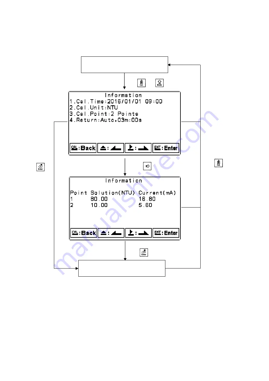
TC-100 Calibration Information 

Note: TC-100, TC-500, TC-3000 electrodes do not have correction factor function. 


Press          to return 

to measurement mode 

Measurement mode 

Enter Calibration Setup Menu 

Press          and          simultaneously 

Press            for next page. 

Press          to   

confirm it 

Press            to confirm it. 

40

Summary of Contents for TC-7310-RS

Page 1: ...TC 7310 RS Intelligent Turbidity S S Transmitter Operation Manual...

Page 2: ...ng to power supply Meter installation site should be properly ventilated and kept from direct sunlight and high temperature The signal cable requires a special coaxial cable material Cables provided b...

Page 3: ...cal Connection Illustration 9 4 Configuration 4 1 Front Panel Illustration 10 4 2 Keypad 10 4 3 LED Indicators 10 5 Operation 5 1 Measurement Mode 11 5 2 Setup Menu 11 5 3 Calibration Menu 11 5 4 Shor...

Page 4: ...ook 36 7 18 Automatic Return Return 37 8 Calibration Calibration Block Diagram 38 8 1 Calibration Setup Menu 39 8 2 Calibration Security Code Code 41 8 3 Calibration 42 8 3 1 Known Solution Calibratio...

Page 5: ...d proceed to next step Setup Items Function Icon Description Mode Measurement mode 1 Select from TC 100 TC 500 TC 3000 or TCS 1000 electrodes 2 Select display mode from text real time or trace mode 3...

Page 6: ...from power Replace with 3V CR2025 2032 lithium battery RS 485 RS485 serial interface Modbus protocol Digital Filter Take 1 60 serial measurements average continuously and display as the reading follow...

Page 7: ...ight or right page Decrease digit Confirm and proceed to next step Calibration Items Up to Five Point Calibration Function Icon Description Known Sol Calibration by known value solution Correction Cal...

Page 8: ...3 min real time dynamic graph Trace mode Programmable 3 min to 4 week trend graph Analog Output Isolated DC 0 4 20 mA corresponding to main measurement Max load 500 Serial Interface Isolated RS 485 M...

Page 9: ...ole of 138 mm x 138 mm on the panel box and then insert the controller directly into the hole Insert the accessorial mounting bracket from the rear and fix into the pickup groove 2 2 Panel Mounting Il...

Page 10: ...fix with a U shaped pipe clamp optional Order Number 8 34 Sun Shield pipe mounting optional Order No 8 35 8 35 1 Sun Shield wall mounting optional Order No 8 35 8 35 2 Insert rubber plug into unused c...

Page 11: ...Overview of Turbidity S S Transmitter TC 7310 RS 3 1 Rear Panel Illustration 3 2 Terminal Function Illustration POWER WASH Cln REL2 REL1 AC INPUT POWER 4 20mA RS 485 D B G D A S Cal S V V Check Shield...

Page 12: ...SS current output terminal for an external recorder or PLC control 4 20mA Terminal Turbidity SS current output terminal for an external recorder or PLC control Shield Sensor signal shield wire V BROWN...

Page 13: ...al relay Surge absorber External relay Cleaning device Surge absorber M Dose feeder Surge absorber M Dose feeder Surge absorber M Note The transmitter s built in miniature relays are required to be re...

Page 14: ...move left or return to the previous page 2 When adjusting values press this key to increase the value 1 In the parameter set up mode and calibration mode press this key to move right or advance to th...

Page 15: ...urement mode 5 4 Shortcuts 1 Under measurement mode press and hold for 2 seconds to enter Logbook function Press to return to measurement mode 2 Under measurement mode press and hold for 2 seconds to...

Page 16: ...0000 Auto return Auto 3 minutes Code settings OFF Note The factory default calibration setting is No Cal and the calibration value is None This means that the user has not yet calibrated the sensor w...

Page 17: ...ode is the main measurement screen and shows the measurement value and unit temperature compensation mode temperature measurement and unit time and date as seen in the following illustration Main meas...

Page 18: ...re updated after returning to measurement mode When the measured value exceeds a set range of the upper and lower limit the graphics will be presented in the upper and lower limits dotted line Real ti...

Page 19: ...epresenting T 12 and five data sets between each mark The user can set the Turbidity SS graph range under Mode in Settings see section 7 4 The smaller the range the higher the display resolution Trace...

Page 20: ...o REL 2 Lo and the RELAY1 RELAY2 indicator LED will light up 4 When the Analog current output exceeds the upper lower limit the display will flash mg l mA__ mg l mA or ppm mA ppm mA Note The HOLD warn...

Page 21: ...7 Settings Settings Block Diagram Part 1 17...

Page 22: ...Manual Auto ON OFF Adj Bright ness Adj Sensi tivity Adj Bright ness RS 485 Select RTU or ASCII Select Baud Rate Select Parity Set ID Number Logbook Display Logbook History Contrast Adj Contrast Conti...

Page 23: ...ent mode press the two keys and simultaneously to enter the current settings overview Press to enter setup mode to modify the settings if necessary Measurement Mode Setup Menu Press Press or Press Pre...

Page 24: ...to confirm it When an incorrect passcode is entered the display will show Error Code press to re enter or press to exit The first 0 of digits 0000 will start to flash Press or to adjust the value and...

Page 25: ...p mode select Language and press to enter system language selection Select from English Traditional Chinese or Simplified Chinese Enter Mode Unit Setup Press to confirm it Press to confirm it Press or...

Page 26: ...TC 500 TC 3000 electrodes selectable modes NTU FTU FNU For TCS 1000 selectable modes mg l ppm Press to confirm it Press or to select the electrode Press to confirm it Press to confirm it Press or to...

Page 27: ...ress or to select display mode Press or to select display mode Press or to adjust minimum value Press to confirm it Press to confirm it Press to confirm it Press to confirm it Press or _ to adjust sec...

Page 28: ...retrieving the sensor for calibration A PDT icon will display on the main screen above the pH unit if the product is adjusted see section 6 4 Enter Relay 1 Setup Press to confirm it Users may compare...

Page 29: ...o adjust Setting Point SP value Press or to select to activate Relay 1 If turned off the menu will proceed to setup of Relay 2 Press to confirm it Press to confirm it Press or to select Relay 1 as Hi...

Page 30: ...lect whether to turn on Relay 2 or not If OFF the guide menu will go to setup of Wiper Press to confirm it Press to confirm it Press or to select Hi point or Lo point alarm of Relay 2 Press to confirm...

Page 31: ...manual to configure automatic cleaning interval TC 100 Auto Electrode default is 30 minute interval Manual Configure from 2 to 29 minutes TC 500 TC 3000 TCS 1000 Auto Electrode default is 10 minute in...

Page 32: ...or deionized water for zero point calibration Note When performing zero point calibration factory default electrode output signals will be altered The transmitter will display the 2mA current sent fr...

Page 33: ...hen entering settings menu or calibration menu while the clean function is activated the instrument will automatically stop the cleaning action Press or to select to activate cleaning test If turned O...

Page 34: ...mA The exceptional output values can be used as an indication for determination failure Under HOLD measurement status the current output maintains the last output value before HOLD status For the con...

Page 35: ...ion even if the power supply is cut off due to an internal battery If this fails please replace the 3V CR2025 Li battery inside the transmitter Enter RS 485 Communication Setup Press to confirm it Pre...

Page 36: ...l output maintains the last output value before hold Press or to select RTU or ASCII mode Enter Sample Measurement Average Digital Filter Setup Press or to set the ID number of the transmitter The val...

Page 37: ...the number of sample measurements to be averaged for each reading to increase the stability of the displayed measurement The greater the number the more stable the measurement value the smaller the nu...

Page 38: ...ht is off When a button is pressed it will enter touch on status Auto setting Transmitter will activate or deactivate the backlight according to the ambient lighting When a button is pressed it will e...

Page 39: ...ast After entering setup mode select Contrast and press to adjust the display contrast 2 1 0 1 2 light to dark Enter Logbook Setup Press to confirm it Press to confirm it Press or to select display co...

Page 40: ...ay up to 50 important events and error diagnosis records The user can read important events via Logbook or Modbus For detailed Modbus definitions of events please see to section 9 2 Modbus Address and...

Page 41: ...quires the user to exit setup menu manually while Auto will set the display to automatically exit the setup menu and return to measurement mode after a period of time without pressing any keys Press o...

Page 42: ...rst Buffer Range Select Second Buffer Range Return to previous level or action Correction Factor Select TCS 1000 Electrode TCS 1000 TC 100 TC 500 TC 3000 Display Current from Electrode Adjust Second C...

Page 43: ...rn to measurement mode If you need to re calibrate the system press to enter calibration setup menu If the calibration time shows OFF it represents that the clock function has been turned off TCS 1000...

Page 44: ...100 TC 500 TC 3000 electrodes do not have correction factor function Press to return to measurement mode Measurement mode Enter Calibration Setup Menu Press and simultaneously Press for next page Pres...

Page 45: ...ress to exit the calibration menu The first 0 of digits 0000 will start to flash Press or to adjust the value then press to confirm it and proceed to the next digit Select to turn on or turn off code...

Page 46: ...ot easily acquired The transmitter is able to use turbidity standard solution to calibrate and adjust the suspended solids measurement via a correction factor 8 3 1 Known Solution Calibration 8 3 1 1...

Page 47: ...ulti point calibration Press or to select the second point closest to the known solution value Press to complete single point calibration Press or to adjust the MLSS standard solution value Rinse the...

Page 48: ...into the first solution for measurement The sensor will display the current received Wait until the value is stable Press to directly display the result or wait for the transmitter to automatically co...

Page 49: ...procedure correction factor adjustment screen will follow Users may also directly enter the correction factor adjustment screen from setup mode Known Solution Calibration Display Calibration Result Ri...

Page 50: ...o will set the display to automatically exit the setup menu and return to measurement mode after a period of time without pressing any keys Note The return function for setup menu and calibration setu...

Page 51: ...e safety risks 2 Use 120 ohm impedance matching resistors at the signal cable terminals D B and D A of the terminal devices to effectively reduce or eliminate signal reflection Note Three common cause...

Page 52: ...istance transmission it is recommended to use cables that are specifically design for RS 485 4 When communicating all equipment within the network should be consistently kept in the same transfer mode...

Page 53: ...tes Information Type Description of Data Transmission Default Value Note 0000H None 0001H R Equipment s ID 2 USHORT 1 247 1 0002H R Transmitter Model 6 USHORT ASCII Code TC7310 0005H R Communication P...

Page 54: ...ness 2 USHORT 0 AUTO 2 1 ON 2 OFF 0022H 2 SHORT 2 Highest Brightness 0 SHORT 1 High Brightness SHORT 0 Standard SHORT 1 Low Brightness SHORT 2 Lowest Brightness 0023H R W Backlight Sensitivity 2 SHORT...

Page 55: ...e transmission order will be CC CD 41 C8 For detailed description please refer to section 9 3 Modbus example description Note 3 USHORT represents unsigned short integer Note 4 Event Logbook ID If the...

Page 56: ...t 0037H 0050H Factory Reserved Function Code 01H Modbus Response Dispersion Parameter Logic Address Item BIT Description Default Value Note 0070H LO Alarm 1 Contact on 0 Contact off 0071H Hi Alarm 1 C...

Page 57: ...tes Information Type Description of Data Transmission Default Value Note 0000H None 0001H R Equipment s ID 2 USHORT 1 247 1 0002H R Transmitter Model 6 USHORT ASCII Code TC7310 0005H R Communication P...

Page 58: ...ness 2 USHORT 0 AUTO 2 1 ON 2 OFF 0022H 2 SHORT 2 Highest Brightness 0 SHORT 1 High Brightness SHORT 0 Standard SHORT 1 Low Brightness SHORT 2 Lowest Brightness 0023H R W Backlight Sensitivity 2 SHORT...

Page 59: ...e transmission order will be CC CD 41 C8 For detailed description please refer to section 9 3 Modbus example description Note 3 USHORT represents unsigned short integer Note 4 Event Logbook ID If the...

Page 60: ...t 0037H 0050H Factory Reserved Function Code 01H Modbus Response Dispersion Parameter Logic Address Item BIT Description Default Value Note 0070H LO Alarm 1 Contact on 0 Contact off 0071H Hi Alarm 1 C...

Page 61: ...e Hi CC No of Registers Hi 00 Register value Lo CD No of Registers Lo 02 Register value Hi 41 LRC C5 Register value Lo C8 LRC 56 RTU Mode Request Response Message Framing Hex Message Framing Hex ID Ad...

Page 62: ...new standard solution 2 Maintain or replace electrode and make another calibration Error5 Incorrect passcode ERROR CODE Re enter passcode Error6 No sensor connection or sensor failure 1 Please check i...

Page 63: ......

Page 64: ...ane 169 Kangning St Xizhi Dist New Taipei City Taiwan R O C Tel 886 2 2695 9688 Fax 886 2 2695 9693 e mail suntex ms1 hinet net www suntex com tw en 5040E TC 7310 RS Technical data subject to alternat...

Reviews: