Section 5
MAINTENANCE
24
2. With the service valve closed, set the engine low
speed (idle) to its specified setting with the idle
stop screw on the engine injector pump.
NOTE
Operation at speeds below the minimum idle
speeds shown in Section 3 under Specifications
will damage the compressor. Extended operation
below those speeds will induce coupling and/or
compressor failures.
3. Adjust the pressure regulator so that the com-
pressor maintains 117 psig (8.1 bar).
4. Gradually open the service valve to atmosphere
until the engine comes up in speed and sump
pressure is held at 100 psig (6.9 bar). At this
point, set the engine high speed to its specified
setting by adjusting the high idle threaded rod lo-
cated on the engine speed control. To raise or
lower the speed, lengthen or shorten the rod re-
spectively.
5. Open the service valve to 100 psig (6.9 bar) (rated
full load pressure) and recheck top engine
speed and control response. Close the service
valve and allow the compressor to cycle and re-
check low engine speed (idle).
The following explanation applies to “H” compres-
sor with dual pressure controls.
1. Start the compressor and allow the engine to
warm---up to normal operating temperature with
the service valve closed and the pressure selec-
tor switch set to the “low” position.
2. Follow the procedure for setting the controls at
100 psig (6.9 bar) rated full load pressure as de-
scribed in Steps 2 through 5 above.
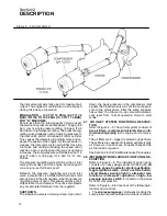
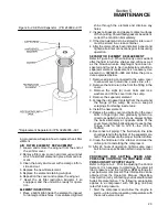
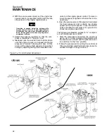
Figure 5---4 Control System Adjustment
175/185
185H
Summary of Contents for 175
Page 6: ...NOTES ...
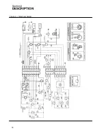
Page 22: ...Section 2 DESCRIPTION 16 Figure 2 7 Electrical System ...
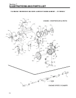
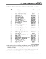
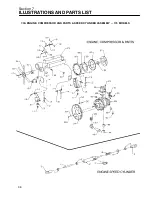
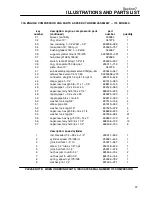
Page 52: ...Section 7 ILLUSTRATIONS AND PARTS LIST 46 7 4A RADIATOR COMPRESSOR FLUID SYSTEM 175 MODELS ...
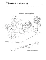
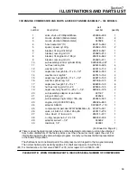
Page 54: ...Section 7 ILLUSTRATIONS AND PARTS LIST 48 7 4A RADIATOR COMPRESSOR FLUID SYSTEM 175 MODELS ...
Page 78: ...Section 7 ILLUSTRATIONS AND PARTS LIST 72 7 9B ELECTRICAL PARTS 185 185H MODELS ...
Page 80: ...Section 7 ILLUSTRATIONS AND PARTS LIST 74 7 10 INSTRUMENT PANEL PARTS ALL MODELS ...
Page 82: ...Section 7 ILLUSTRATIONS AND PARTS LIST 76 7 11A AIR INLET AND EXHAUST 175 MODELS ...
Page 84: ...Section 7 ILLUSTRATIONS AND PARTS LIST 78 7 11B AIR INLET AND EXHAUST 185 185H MODELS ...
Page 86: ...Section 7 ILLUSTRATIONS AND PARTS LIST 80 7 12 FUEL TANK CONNECTIONS ALL MODELS ...
Page 88: ...Section 7 ILLUSTRATIONS AND PARTS LIST 82 7 13A CANOPY PARTS 175 MODELS ...
Page 90: ...Section 7 ILLUSTRATIONS AND PARTS LIST 84 7 13B CANOPY PARTS 185 185H MODELS ...
Page 92: ...Section 7 ILLUSTRATIONS AND PARTS LIST 86 7 14 DECALS ...
Page 94: ...Section 7 ILLUSTRATIONS AND PARTS LIST 88 7 14 DECALS ...
Page 96: ...Section 7 ILLUSTRATIONS AND PARTS LIST 90 7 14 DECALS ...
Page 99: ......

