Section 7
ILLUSTRATIONS AND PARTS LIST
41
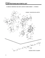
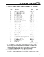
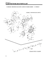
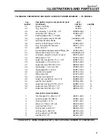
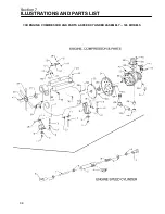
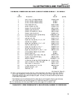
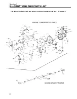
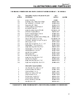
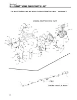
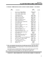
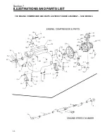
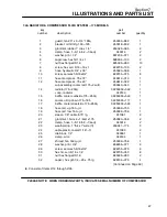
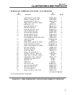
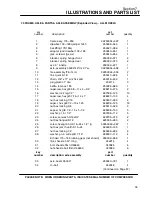
7.3B ENGINE, COMPRESSOR AND PARTS & SPEED CYLINDER ASSEMBLY -- 185 MODELS
key
description: engine, compressor & parts
part
number
(continued)
number
quantity
31
spacer, fan 185q
409984
1
32
coupling, eng---compr lord---250p
250034---921
1
33
tee, reducing 1---1/2x1/2x1---1/2”
802206---026
1
34
fan,suction 20” 185jd
250005---178
1
35
bushing,taper sd 1.50”bore str
250035---375
1
36
key,square class #2
250040---924
1
37
support,cylinder mount 175/375
02250061---551
1
38
pin,drive coupling 250 jd
250035---041
8
39
switch, temp 215deg f 1/2”x1/4
250025---207
1
40
plug, pipe 1/2” 3000 stl
807800---020
1
41
sub assembly,regulator valve 375dpq---2w
250040---047
1
42
elbow,check valve 1/4t x 1/8p
02250058---275
1
43
connector, straight 1/4 t pls 1/4 npt m
250018---428
1
44
elbow, pipe 1---1/2
801515---060
1
45
capscrew, hex gr5 5/8---11 x 1---1/2”
828610---150
4
46
nipple,pipe 1---1/2 x 6.0 sc 40
822124---060
1
47
capscrew, ferry hd 5/16 x 2 1/4”
828405---225
4
48
nipple,pipe 1---1/2 x cl sc 80
822224---000
1
49
nipple,pipe 3/4 x cl sc 80
822212---000
1
50
washer, lock reg 5/8”
837510---156
4
51
elbow, pipe 3/4
801515---030
1
52
washer, lock reg 5/16”
837505---078
4
53
capscrew, ferry hd 3/8 x 1 1/4”
828406---125
19
54
washer, lock reg 3/8”
837506---094
14
55
capscrew, ferry hd 3/8 x 1 1/2”
828406---150
8
56
capscrew, hex gr5 3/8---16 x 2 1/4
828606---225
2
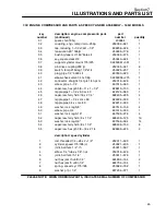
description: speed cylinder
1
rod, threaded 1/4---28 x 2---1/2”
250011---590
1
2
cylinder, speed 175/185 jd
250021---405
1
3
joint, ball fem. 1/4” rh
250011---597
1
4
elbow, 1/4” tube x 1/8” npt
250018---429
1
5
joint, ball fem. lh 1/4”
250011---578
1
6
nut,hex jam rh unfin 1/4”
824604---164
2
7
nut,hex jam lh unfin 1/4”
824704---164
1
8
spring, speed cyl. 175/185
250022---782
1
9
washer, pl b r 1/4”
837204---071
1
PLEASE NOTE: WHEN ORDERING PARTS, INDICATE SERIAL NUMBER OF COMPRESSOR
Summary of Contents for 175
Page 6: ...NOTES ...
Page 22: ...Section 2 DESCRIPTION 16 Figure 2 7 Electrical System ...
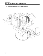
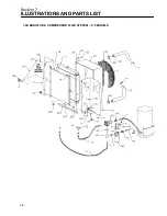
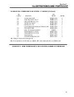
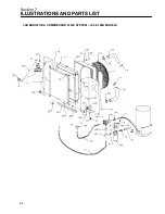
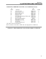
Page 52: ...Section 7 ILLUSTRATIONS AND PARTS LIST 46 7 4A RADIATOR COMPRESSOR FLUID SYSTEM 175 MODELS ...
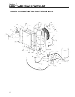
Page 54: ...Section 7 ILLUSTRATIONS AND PARTS LIST 48 7 4A RADIATOR COMPRESSOR FLUID SYSTEM 175 MODELS ...
Page 78: ...Section 7 ILLUSTRATIONS AND PARTS LIST 72 7 9B ELECTRICAL PARTS 185 185H MODELS ...
Page 80: ...Section 7 ILLUSTRATIONS AND PARTS LIST 74 7 10 INSTRUMENT PANEL PARTS ALL MODELS ...
Page 82: ...Section 7 ILLUSTRATIONS AND PARTS LIST 76 7 11A AIR INLET AND EXHAUST 175 MODELS ...
Page 84: ...Section 7 ILLUSTRATIONS AND PARTS LIST 78 7 11B AIR INLET AND EXHAUST 185 185H MODELS ...
Page 86: ...Section 7 ILLUSTRATIONS AND PARTS LIST 80 7 12 FUEL TANK CONNECTIONS ALL MODELS ...
Page 88: ...Section 7 ILLUSTRATIONS AND PARTS LIST 82 7 13A CANOPY PARTS 175 MODELS ...
Page 90: ...Section 7 ILLUSTRATIONS AND PARTS LIST 84 7 13B CANOPY PARTS 185 185H MODELS ...
Page 92: ...Section 7 ILLUSTRATIONS AND PARTS LIST 86 7 14 DECALS ...
Page 94: ...Section 7 ILLUSTRATIONS AND PARTS LIST 88 7 14 DECALS ...
Page 96: ...Section 7 ILLUSTRATIONS AND PARTS LIST 90 7 14 DECALS ...
Page 99: ......

