Section 7
ILLUSTRATIONS AND PARTS LIST
69
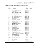
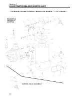
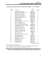
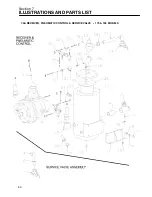
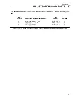
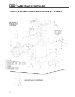
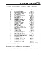
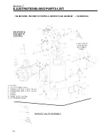
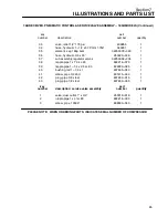
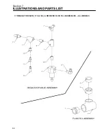
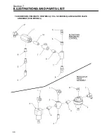
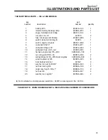
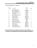
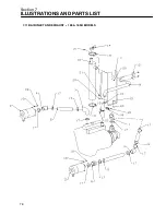
7.8 BLOWDOWN PNEUMATIC CONTROLS (175 & 185 MODELS) & REGULATOR VALVE
ASSEMBLY (185H MODELS)
key
blowdown pneumatic controls
part
number
description
number
quantity
1
valve, blowdown 1/4” npt
(I)
250025---655
1
2
elbow, 1/4” tube x 1/4” npt
250018---430
1
3
orifice, .093 x .125m x .125f
250014---060
1
4
silencer, air ejection
248755
1
5
connector,1/8” tube x 1/8mnpt/str
250038---121
1
6
nipple,pipe hx 1/4”
860404---025
1
7
tee,straight 1/4
802415---010
2
8
nipple,pipe 1/4 x cl sc 80
822204---000
1
9
bushing,red 1/4x1/8
807600---005
2
10
nipple,pipe 1/4 x 1.5 sc 80
822204---015
1
key
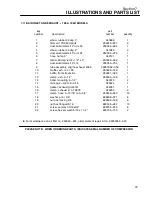
regulator valve assembly
part
number
description
number
quantity
1
elbow, 1/4” tube x 1/4” npt
250018---430
3
2
valve, regulator back press.
(II)
041517
1
3
valve, pressure regulator
(III)
250017---280
1
4
nipple,pipe 1/4 x cl sc 80
822204---000
3
5
cross, pipe 150# 1/4
801315---010
1
6
plug, pipe 1/4 steel
807800---010
1
(I)
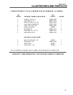
For maintenance on blowdown valve no. 250025---655, order repair kit no. 250031---772.
(II)
For maintenance on regulator valve no. 041517, order repair kit no. 041742.
(III)
For maintenance on regulator valve no. 250017---280, order repair kit no. 250019---453.
PLEASE NOTE: WHEN ORDERING PARTS, INDICATE SERIAL NUMBER OF COMPRESSOR
Summary of Contents for 175
Page 6: ...NOTES ...
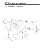
Page 22: ...Section 2 DESCRIPTION 16 Figure 2 7 Electrical System ...
Page 52: ...Section 7 ILLUSTRATIONS AND PARTS LIST 46 7 4A RADIATOR COMPRESSOR FLUID SYSTEM 175 MODELS ...
Page 54: ...Section 7 ILLUSTRATIONS AND PARTS LIST 48 7 4A RADIATOR COMPRESSOR FLUID SYSTEM 175 MODELS ...
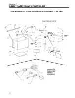
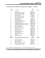
Page 78: ...Section 7 ILLUSTRATIONS AND PARTS LIST 72 7 9B ELECTRICAL PARTS 185 185H MODELS ...
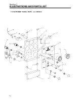
Page 80: ...Section 7 ILLUSTRATIONS AND PARTS LIST 74 7 10 INSTRUMENT PANEL PARTS ALL MODELS ...
Page 82: ...Section 7 ILLUSTRATIONS AND PARTS LIST 76 7 11A AIR INLET AND EXHAUST 175 MODELS ...
Page 84: ...Section 7 ILLUSTRATIONS AND PARTS LIST 78 7 11B AIR INLET AND EXHAUST 185 185H MODELS ...
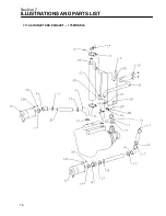
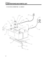
Page 86: ...Section 7 ILLUSTRATIONS AND PARTS LIST 80 7 12 FUEL TANK CONNECTIONS ALL MODELS ...
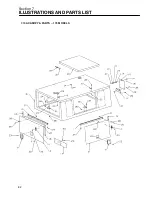
Page 88: ...Section 7 ILLUSTRATIONS AND PARTS LIST 82 7 13A CANOPY PARTS 175 MODELS ...
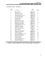
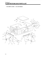
Page 90: ...Section 7 ILLUSTRATIONS AND PARTS LIST 84 7 13B CANOPY PARTS 185 185H MODELS ...
Page 92: ...Section 7 ILLUSTRATIONS AND PARTS LIST 86 7 14 DECALS ...
Page 94: ...Section 7 ILLUSTRATIONS AND PARTS LIST 88 7 14 DECALS ...
Page 96: ...Section 7 ILLUSTRATIONS AND PARTS LIST 90 7 14 DECALS ...
Page 99: ......

