Section 4
OPERATION
19
4.1 GENERAL
While Sullair has built into this compressor a compre-
hensive array of controls and indicators to assure
you that it is operating properly, you will want to rec-
ognize and interpret the reading which will call for
service or indicate the beginning of a malfunction.
Before starting your Sullair compressor, read this
section thoroughly and familiarize yourself with the
controls and indicators --- their purpose, location and
use.
4.2 PURPOSE OF CONTROLS
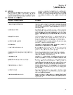
CONTROL OR INDICATOR
PURPOSE
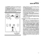
TOGGLE IGNITION SWITCH
Turn this switch to the
“
on” position to energize the electri-
cal system of the compressor. Turn to the
“
off” position to
shut the compressor down. This switch is located on the in-
strument panel.
STARTER BUTTON
Push this button along with the override button to start the
compressor. Release the starter switch as soon as the en-
gine is engaged, but hold the override button for 5 to 10 sec-
onds or until the engine oil pressure reaches 20 psig (1.4
bar).
OVERRIDE BUTTON
Located on the instrument panel, it is used to bypass the oil
pressure switch when starting the engine. It must be
pressed simultaneously with pushing the starter button.
AIR PRESSURE GAUGE
Continually monitors the pressure inside the receiver sump
at various load and unload conditions.
HOURMETER
Indicates the accumulated hours of operation. Useful for
planning and logging service schedules.
FLUID LEVEL SIGHT GLASS
Monitors the fluid level in the sump. Proper level is always
centered in the sight glass. Check the level when the com-
pressor is shut down and on level ground.
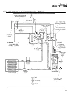
COMPRESSOR DISCHARGE TEMPERATURE
Opens the electrical circuit to shut down the compres---
SWITCH
sor when the discharge temperature reaches a specific
value (see Section 3, Specifications).
THERMAL VALVE
Functions as a temperature regulator directing the com-
pressor fluid either to the cooler or to the compressor unit.
MINIMUM PRESSURE/CHECK VALVE
Maintains the minimum of 55 psig (3.8 bar) in the compres-
sor sump. This valve restricts receiver air discharge from re-
ceiver/sump when pressure falls to 55 psig (3.8 bar); how-
ever, full flow is allowed at normal operating pressures.
PRESSURE RELIEF VALVE
Opens sump pressure to the atmosphere should pressure
inside the sump exceed 140 psig (9.7 bar) or 175 psig (12.1
bar) on 185H.
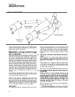
AIR INLET VALVE
Regulates the amount of air allowed to enter the air inlet
valve. This regulation is determined by a pressure signal
from the pressure regulator.
PRESSURE REGULATOR (S)
Allows a pressure signal to reach the engine speed control
cylinder and the air inlet valve to control air delivery accord-
ing to demand.
Summary of Contents for 175
Page 6: ...NOTES ...
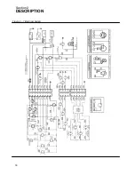
Page 22: ...Section 2 DESCRIPTION 16 Figure 2 7 Electrical System ...
Page 52: ...Section 7 ILLUSTRATIONS AND PARTS LIST 46 7 4A RADIATOR COMPRESSOR FLUID SYSTEM 175 MODELS ...
Page 54: ...Section 7 ILLUSTRATIONS AND PARTS LIST 48 7 4A RADIATOR COMPRESSOR FLUID SYSTEM 175 MODELS ...
Page 78: ...Section 7 ILLUSTRATIONS AND PARTS LIST 72 7 9B ELECTRICAL PARTS 185 185H MODELS ...
Page 80: ...Section 7 ILLUSTRATIONS AND PARTS LIST 74 7 10 INSTRUMENT PANEL PARTS ALL MODELS ...
Page 82: ...Section 7 ILLUSTRATIONS AND PARTS LIST 76 7 11A AIR INLET AND EXHAUST 175 MODELS ...
Page 84: ...Section 7 ILLUSTRATIONS AND PARTS LIST 78 7 11B AIR INLET AND EXHAUST 185 185H MODELS ...
Page 86: ...Section 7 ILLUSTRATIONS AND PARTS LIST 80 7 12 FUEL TANK CONNECTIONS ALL MODELS ...
Page 88: ...Section 7 ILLUSTRATIONS AND PARTS LIST 82 7 13A CANOPY PARTS 175 MODELS ...
Page 90: ...Section 7 ILLUSTRATIONS AND PARTS LIST 84 7 13B CANOPY PARTS 185 185H MODELS ...
Page 92: ...Section 7 ILLUSTRATIONS AND PARTS LIST 86 7 14 DECALS ...
Page 94: ...Section 7 ILLUSTRATIONS AND PARTS LIST 88 7 14 DECALS ...
Page 96: ...Section 7 ILLUSTRATIONS AND PARTS LIST 90 7 14 DECALS ...
Page 99: ......

