Section 4
OPERATION
20
4.2 PURPOSE OF CONTROLS (Continued)
CONTROL OR INDICATOR
PURPOSE
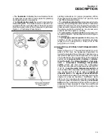
BLOWDOWN VALVE
Vents sump pressure to the atmosphere at shutdown.
ALTERNATOR WARNING LAMP
Indication of impending shutdown of compressor due to al-
ternator failure.
IDLE WARM---UP VALVE
Maintains a closed air inlet valve for reduced compressor
load on start---up. When sufficient warm---up is reached,
push idle warm---up button on control panel for full opera-
tion.The valve will reset automatically for start mode after
compressor is shutdown and the air pressure is released.
PRESSURE SELECTOR SWITCH (185H)
Allows compressor operation in the ”low” range from 55 to
110 psig (3.8 to 7.6 bar) or in the ”high” range from 55 to
160 psig (3.8 to 11 bar).
4.3 START--UP PROCEDURE
The following procedure should be used to make the
initial start---up of your compressor:
1. Position the compressor on a level surface so that
proper amounts of liquid can be added if neces-
sary.
(I)
2. Check oil and fluid levels both in the engine and
the cooling system(s). Maintain the proper level;
add if necessary.
3. Fill the fuel tank.
4. Crack open one service line.
5. Bleed fuel injection lines if necessary (see Engine
Operator’s Manual).
6. Turn toggle switch to the
“
ON
” position.
7. Place the pressure selector switch in the ”low”
position (185H).
8. Push the
OVERRIDE
and
START
button. As en-
gine engages, release
START
button, but hold
the
OVERRIDE
button for approximately 5---10
seconds or until engine oil pressure reaches 20
psig (1.4 bar) and then release.
9. Allow for sufficient warm---up of compressor, then
push idle warm---up button for full compressor
operation.
10. Close all doors in order to maintain proper noise
control.
11. After the initial run, shut the compressor down
and refill the radiator and compressor fluid sump
as required. Tighten any loose fittings and check
fan belt tension.
(I)
The radiator is filled with a 50/50 mixture of ethyl-
ene glycol and water at the factory before shipment.
4.4 SUBSEQUENT START--UP PROCEDURE
On subsequent starts, follow the procedure ex-
plained below:
1. Check engine oil, water and fuel levels.
2. Check compressor fluid level (should be half of
sight glass).
3. Check dust collectors and clean if necessary.
4. Crack open service valve.
5. Bleed fuel injection lines if necessary (see Engine
Operator’s Manual).
6. Turn toggle switch to the
ON
position.
7. Place the pressure selector switch in the ”low”
position (185H).
8. In cold weather use starting aid if necessary.
9. Push
OVERRIDE
button and
START
switch. As
engine engages, release
START
switch, but hold
the
OVERRIDE
button for approximately 5---10
seconds or until engine oil pressure reaches 20
psig (1.4 bar), and then release.
10. Allow for sufficient warm up of compressor before
operating.
11. After warm---up, push idle warm---up button for
full operation.
4.5 SHUTDOWN PROCEDURE
To shut the compressor down, close the service
valves and run compressor for approximately 5 min-
utes to allow the compressor to cool down and turn
the ignition switch to the
OFF
position. In case of
emergency where immediate shutdown is required,
this procedure is not necessary. The ignition switch
should be put in the
OFF
position immediately.
Summary of Contents for 175
Page 6: ...NOTES ...
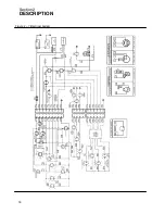
Page 22: ...Section 2 DESCRIPTION 16 Figure 2 7 Electrical System ...
Page 52: ...Section 7 ILLUSTRATIONS AND PARTS LIST 46 7 4A RADIATOR COMPRESSOR FLUID SYSTEM 175 MODELS ...
Page 54: ...Section 7 ILLUSTRATIONS AND PARTS LIST 48 7 4A RADIATOR COMPRESSOR FLUID SYSTEM 175 MODELS ...
Page 78: ...Section 7 ILLUSTRATIONS AND PARTS LIST 72 7 9B ELECTRICAL PARTS 185 185H MODELS ...
Page 80: ...Section 7 ILLUSTRATIONS AND PARTS LIST 74 7 10 INSTRUMENT PANEL PARTS ALL MODELS ...
Page 82: ...Section 7 ILLUSTRATIONS AND PARTS LIST 76 7 11A AIR INLET AND EXHAUST 175 MODELS ...
Page 84: ...Section 7 ILLUSTRATIONS AND PARTS LIST 78 7 11B AIR INLET AND EXHAUST 185 185H MODELS ...
Page 86: ...Section 7 ILLUSTRATIONS AND PARTS LIST 80 7 12 FUEL TANK CONNECTIONS ALL MODELS ...
Page 88: ...Section 7 ILLUSTRATIONS AND PARTS LIST 82 7 13A CANOPY PARTS 175 MODELS ...
Page 90: ...Section 7 ILLUSTRATIONS AND PARTS LIST 84 7 13B CANOPY PARTS 185 185H MODELS ...
Page 92: ...Section 7 ILLUSTRATIONS AND PARTS LIST 86 7 14 DECALS ...
Page 94: ...Section 7 ILLUSTRATIONS AND PARTS LIST 88 7 14 DECALS ...
Page 96: ...Section 7 ILLUSTRATIONS AND PARTS LIST 90 7 14 DECALS ...
Page 99: ......

